| CPC D06F 58/20 (2013.01) [B08B 3/02 (2013.01); D06F 58/24 (2013.01); D06F 58/206 (2013.01); D06F 58/30 (2020.02)] | 19 Claims |

|
1. A clothes treatment apparatus comprising:
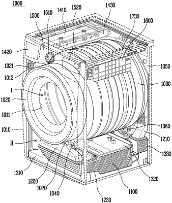
a drum configured to accommodate an object to be treated, the drum defining a front opening and a rear opening;
a base that is disposed below the drum and defines at least a portion of an air circulation flow path configured to guide air discharged from the front opening of the drum to the rear opening of the drum;
a heat exchanger disposed in the air circulation flow path;
a circulation fan disposed in the air circulation flow path at a downstream side relative to the heat exchanger, the circulation fan being configured to generate air flow in the air circulation flow path to supply the air to the rear opening of the drum;
a water collection part disposed at the base and configured to collect condensate water generated based on circulating the air through the air circulation flow path, the water collection part comprising a surrounding region that extends along a periphery of the water collection part and a bottom region that is disposed lower than the surrounding region;
a cover that covers the water collection part; and
a trap disposed at the water collection part and configured to restrict introduction of external air into the air circulation flow path through the water collection part, the trap comprising a bottom surface disposed lower than the surrounding region of the water collection part and configured to collect the condensate water therein,
wherein the trap comprises:
an upwardly-protruding rib that protrudes from the bottom surface of the trap toward the cover and has an upper end spaced apart from the cover, and
a downwardly-protruding rib that protrudes from the cover toward the bottom surface of the trap and has a lower end spaced apart from the bottom surface of the trap,
wherein the upwardly-protruding rib and the downwardly-protruding rib have cylindrical shapes that are concentric to each other and have different diameters,
wherein the upwardly-protruding rib comprises a plurality of first ribs that have cylindrical shapes and are arranged about a center, and
wherein the downwardly-protruding rib comprises a plurality of second ribs that are arranged about the center and alternately disposed with the plurality of first ribs in a direction away from the center.
|