| CPC H01R 24/76 (2013.01) [H01R 9/24 (2013.01); H01R 13/6315 (2013.01); H01R 13/748 (2013.01); H01R 24/20 (2013.01)] | 8 Claims |

|
1. A terminal connection unit comprising:
a current-carrying member including a connection portion configured to be connected to a terminal fitting provided at a terminal end of an electric wire; and
a support portion configured to fixedly support the current-carrying member,
wherein the current-carrying member includes a fixing portion configured to be fixed to the support portion, and an extendable portion that couples the connection portion and the fixing portion and is extendable and contractable in a first direction,
the support portion includes an attachment portion configured to be attached to the connection portion, the attachment portion being displaceable in the first direction,
the support portion includes a through hole that is elongated in the first direction,
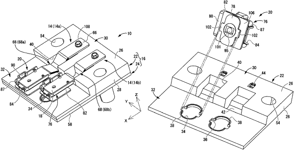
the attachment portion includes a holder configured to hold the connection portion, an elongated locking plate arranged facing a bottom surface of the holder across a gap, and a coupling portion that couples the locking plate to the bottom surface,
the locking plate is insertable into the through hole when a lengthwise direction of the locking plate is matched with the first direction, and the attachment portion is attached at a normal position relative to the support portion by inserting the locking plate into the through hole and rotating the holder such that the lengthwise direction is orthogonal to the first direction, and
when the attachment portion is at the normal position, the locking plate engages with a peripheral edge portion of the through hole, and the attachment portion is attached to the support portion in a state where detachment is prevented and displacement in the first direction is allowed.
|