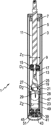
| CPC F16F 9/3242 (2013.01) [F16F 9/3271 (2013.01); F16F 9/49 (2013.01)] | 7 Claims |

|
1. A vibration damper (1) having a hydraulic compression stop (25), comprising:
a cylinder (3) filled with a damping medium;
a piston rod (5) guided in the cylinder (3) in an axially movable manner, wherein the cylinder (3) has therewithin a first piston (9) fastened to the piston rod (5) and slidable on an inner wall of the cylinder (3);
a second piston (19) arranged on the piston rod (5) at an axial distance from the first piston (9), the second piston (19) having a diameter smaller than that of the first piston (9), and being slidable in a pressure cylinder (21) depending on a stroke position of the piston rod (5),
wherein the pressure cylinder (21) is formed with respect to the cylinder (3) by a separate plastic pressure sleeve (35) having a bottom (36),
wherein the pressure cylinder (21) is supported on a metal base (37) via a holding connection, the pressure sleeve (21) having, in a direction of the base (37), an encircling centering ring (53) configured to position the pressure sleeve (35) with respect to the base (37), and a bottom (57) of the base (37) is coated on its top sides (59; 61) with plastic, and
wherein the bottom (36) of the pressure sleeve (35) and a coating surface (63) of the base (37) on a side of the base (37) facing away from the pressure sleeve (35) are connected to each other via at least one web (65),
wherein the base (37) has at least one step (69), and wherein an outer lateral surface (31) of the pressure sleeve (35) extends as far as a radial supporting surface (73) of the step (69);
at least one connecting opening (77) between the outer lateral surface (31) of the pressure sleeve (35), an inner side of the base (37) being formed within the step (69), wherein an outer side of the centering ring (53) forms at least one portion of an encircling collecting groove (83) which connects the outer lateral surface (31) of the pressure sleeve (35) to a plurality of connecting openings (77) in the base (37);
a base area (85) of the collecting groove (83) arranged obliquely with respect to a longitudinal axis (87) of the pressure sleeve (35); and
a supporting ring (71) of the base (37), the supporting ring carrying the pressure sleeve (35), and having a conical shape in a direction of the bottom (36) of the pressure sleeve (35).
|