| CPC F15B 11/08 (2013.01) [B60T 13/141 (2013.01); B62D 5/30 (2013.01); F15B 1/022 (2013.01); F16H 61/4096 (2013.01); F16H 61/4157 (2013.01); F16H 61/4165 (2013.01); B60T 2270/402 (2013.01); F15B 2211/205 (2013.01); F15B 2211/4053 (2013.01); F15B 2211/625 (2013.01); F15B 2211/6355 (2013.01); F15B 2211/85 (2013.01); F15B 2211/8752 (2013.01)] | 7 Claims |

|
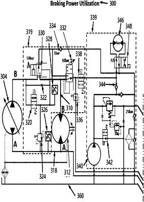
1. A hydraulic circuit comprising:
a pump that is configured to be driven by a prime motor;
a secondary motor fluidly that is coupled to said pump by a supply line and a return line; said secondary motor includes a high-pressure port side;
a fluid output from said secondary motor;
a first work function circuit that is fluidly coupled to said supply line and said return line; said first work function circuit includes a first work function actuator and motor control circuit; said motor control circuit is configured to a) minimize overspeeding of said prime motor, and/or b) assist in acceleration of said secondary motor; said first work function actuator is selected from the group consisting of: a) a fan drive motor, b) a generator motor, c) a cylinder, d) a rotary actuator, e) a work function motor, and f) an actuator motor that is loaded during dynamic motor braking;
a heat control circuit that is configured to reduce heat generation; said heat control circuit includes one or more of a fan pump and said fan drive motor; and
a valving arrangement that is operative to direct at least a portion of pressurized fluid output from said secondary motor during said dynamic motor braking to said heat control circuit to reduce or prevent said prime motor from overspeeding and/or to reduce heat generation in said first work function circuit; said valving arrangement includes a first pressure valve and a second pressure valve; said first and second pressure valves are configured to be activated after a predetermined pressure is sensed; said first and second pressure valves are configured to facilitate in redirecting at least a portion of said pressurized fluid to said heat control circuit when said first and second pressure valves are activated; said valving arrangement includes a first pressure transducer and a pressure reducing valve; said pressure reducing valve includes a preset setting; said pressure reducing valve is configured to allow said pressurized fluid to be directed to a fluid accumulator when said fluid pressure is at said preset setting or exceeds said preset setting; said first pressure transducer is configured to cause at least one of said first and second pressure valves to be activated when said fluid accumulator is charged at a certain level to thereby direct at least a portion of said pressurized fluid to said heat control circuit.
|