| CPC E04D 13/0722 (2013.01) [E04D 3/366 (2013.01); E04D 13/031 (2013.01); E04D 13/0641 (2013.01); E04D 13/0685 (2013.01); E04D 13/1475 (2013.01); E05Y 2900/154 (2013.01)] | 19 Claims |

|
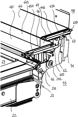
1. A connector arrangement for a flashing assembly for use in a roof window arrangement, said connector arrangement comprising a base connector element configured for being arranged with an exterior side facing an exterior in a mounted state, an interior side opposite the exterior side, and a length direction of the base connector element extending from a first end towards a second end, where the exterior side comprises a base gutter with two longitudinal edges extending between the first and second ends, where the base gutter is open at the second end so that water can drain out of the base gutter, and where an attachment section on the interior side is configured for being attached to a bracket used for connecting a roof window to a load-bearing structure,
the connector arrangement further comprises an elevation element and a top connector element,
said elevation element is connected to the base connector element and supporting the top connector element so that the top connector element is positioned above the base connector element when seen in a height direction extending from the interior side towards the exterior side,
said top connector element comprises a top gutter with two longitudinal edges extending between a first end and a second opposite open end, where a length direction of the top connector element extends from the first end towards the second opposite open end of said top connector, and
when arranged on the elevation element, the top connector element is arranged with its second opposite open end above the gutter of the base connector element and with the length direction of the top connector element extending substantially in parallel to the length direction of the base connector element wherein a first plane extending parallel to an inclination of a roof and passing through a bottom of said top gutter is disposed above a second plane extending parallel to the inclination of the roof and passing through an uppermost portion of said base gutter.
|