| CPC B60C 11/1218 (2013.01) [B60C 11/124 (2013.01); B60C 11/1281 (2013.01); B60C 2011/1213 (2013.01); B60C 2200/06 (2013.01)] | 3 Claims |

|
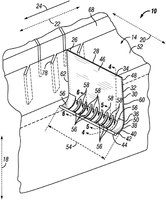
1. A tread for a heavy truck tire, comprising:
an upper surface that is configured for engaging ground, wherein the tread has a radial direction, an axial direction, and a circumferential direction, wherein the tread is directional such that the tread is configured for having a rolling direction that extends in the circumferential direction;
a J shaped sipe, comprising:
a trailing edge;
a leading edge, wherein the trailing edge is forward of the leading edge in the rolling direction;
a main portion that extends from the upper surface, wherein the main portion has an opening at the upper surface and a bottom end opposite the opening in the radial direction; and
a curved portion that extends from the bottom end of the main portion, wherein the curved portion has a bottom curved wall that has a radius r1, wherein the curved portion extends from the bottom end of the main portion forward in the rolling direction, wherein the curved portion has a curved portion end, wherein the curved portion has a top curved wall that faces the bottom curved wall wherein the curved portion has a curved portion thickness t2 that is a distance from the top curved wall to the bottom curved wall and is less than or equal to 1 millimeter;
wherein the J shaped sipe has a teardrop located at the curved portion end, wherein the teardrop has a circular cross-sectional shape;
wherein the main portion is defined by a forward wall and a rearward wall that face one another, wherein the forward wall is forward of the rearward wall in the rolling direction, wherein a main portion thickness t1 is a distance from the forward wall to the rearward wall,
wherein the J shaped sipe has an extension distance d1 that is the distance from the rearward wall to the farthest point of the teardrop from the rearward wall;
wherein the teardrop has a diameter d2;
wherein:
0.2 millimeters≤t1≤2.0 millimeters;
0.0 millimeters≤t2≤1.0 millimeters;
1.0 millimeters≤r1≤10 millimeters;
t1≤d2≤(4.0×t1);
r1≤d1≤(1.1×(r1+d2));
t2≤t1.
|