| CPC B29C 45/125 (2013.01) [B29C 33/0088 (2013.01); B29C 45/14655 (2013.01); B29C 45/322 (2013.01)] | 7 Claims |

|
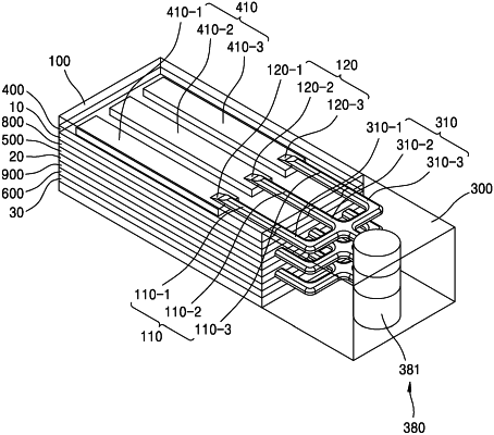
1. A stack molding machine comprising:
an upper mold having formed therein a first runner serving as a path of a resin material;
a first intermediate plate provided under and combined with the upper mold, and having formed therein a first molding connected to the first runner to mold at least a portion on a first substrate placed under the first intermediate plate;
a first injection plate provided under the first intermediate plate, and having formed therein a third runner serving as a path of the resin material;
a second intermediate plate provided under the first injection plate, and having formed therein a second molding connected to the third runner to mold at least a portion on a second substrate placed under the second intermediate plate;
a second injection plate provided under the second intermediate plate, and having formed therein a fourth runner serving as a path of the resin material;
a third intermediate plate provided under the second injection plate, and having formed therein a third molding connected to the fourth runner to mold at least a portion on a third substrate placed under the third intermediate plate; and
a lower mold provided under and combined with the third intermediate plate,
wherein the upper mold comprises a first gate connected to the first molding at an end of the first runner,
wherein the first injection plate comprises a third gate connected to the second molding at an end of the third runner, and
wherein the second injection plate comprises a fourth gate connected to the third molding at an end of the fourth runner.
|