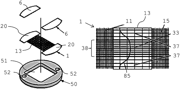
| CPC A24F 40/46 (2020.01) [H05B 1/0277 (2013.01); H05B 3/145 (2013.01); H05B 3/34 (2013.01); H05B 3/36 (2013.01); A24F 40/10 (2020.01); H05B 2203/021 (2013.01)] | 15 Claims |

|
1. A fluid permeable heater assembly for aerosol-generating systems, the fluid permeable heater assembly comprising:
an electrically conductive flat filament arrangement being a mesh and including,
a center surface having a first mesh density,
a first side surface having a second mesh density, the first side surface at least partially overmolded with a polymer configured to withstand temperatures of greater than 300° C.,
a second side surface having the second mesh density, the second side surface at least partially overmolded with the polymer, the first side surface and the second side surface spaced apart in a first direction,
mesh density gradients between the first side surface and the center surface, and between the center surface and the second side surface, the mesh density gradients smoothly transitioning from the first mesh density to the second mesh density,
a central longitudinal region extending from the first side surface to the second side surface, and
an edge region extending through the center surface, the first side surface, and the second side surface, an electrical resistance in the central longitudinal region corresponding to the center surface being lower than an electrical resistance in the edge region corresponding to the center surface, the edge region having fewer filaments than the central longitudinal region, the edge region being adjacent to the central longitudinal region in a second direction different from the first direction;
a first contact point; and
a second contact point, the first contact point and the second contact point configured to electrically contact the flat filament arrangement, a longitudinal axis being defined between the first contact point and the second contact point, a center resistance Rc being the electrical resistance between two points situated on the longitudinal axis, one of the two points being situated at a distance from the first contact point equal to 40 percent of the distance between the first and the second contact point, and the other one of the two points being situated at a distance from the first contact point equal to 60 percent of the distance between the first and the second contact point, a first resistance R1 is an electrical resistance between the first contact point and a point situated on the longitudinal axis at a distance from the first contact point equal to 20 percent of the distance between the first and the second contact point, a second resistance R2 is an electrical resistance between the second contact point and a point situated on the longitudinal axis at a distance from the first contact point equal to 80 percent of the distance between the first and the second contact point, a ratio of the center resistance to the first resistance Rc/R1 ranges from 2 to 400, and a ratio of the center resistance to the second resistance Rc/R2 ranges from 2 to 400.
|