| CPC H02M 3/33573 (2021.05) [H02M 1/08 (2013.01); H02M 3/33584 (2013.01); H02M 3/33592 (2013.01)] | 10 Claims |

|
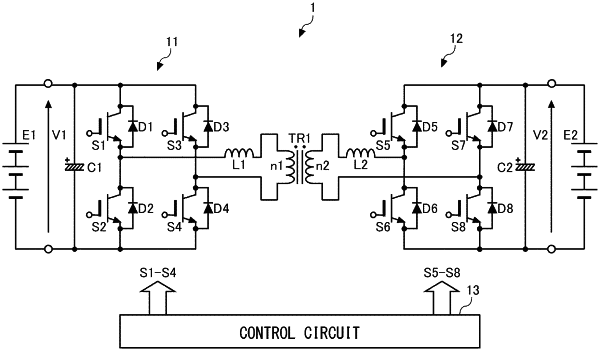
1. A power converter comprising:
a first bridge circuit including a first leg and a second leg, the first leg including a first switching element and a second switching element connected in series, the second leg including a third switching element and a fourth switching element connected in series, and the first leg and the second leg being connected in parallel to a first DC part;
a second bridge circuit including a third leg and a fourth leg, the third leg including a fifth switching element and a sixth switching element connected in series, the fourth leg including a seventh switching element and an eighth switching element connected in series, and the third leg and the fourth leg being connected in parallel to a second DC part;
an insulated transformer connected between the first bridge circuit and the second bridge circuit; and
a control circuit that controls the first switching element to the eighth switching element, wherein
diodes are connected or formed in antiparallel to the first switching element to the eighth switching element, respectively,
for power transfer from the first DC part to the second DC part by stepping up a voltage, the second bridge circuit includes a period in which a secondary winding of the insulated transformer and the second DC part conduct and a period in which ends of the secondary winding of the insulated transformer are short-circuited in the second bridge circuit,
the control circuit
fixes a phase difference between the first leg and the second leg,
variably controls a simultaneous off period of the fifth switching element and the sixth switching element, and
variably controls a simultaneous off period of the seventh switching element and the eighth switching element, and
for power transfer from the first DC part to the second DC part by stepping down a voltage,
the control circuit performs control that includes:
a first pattern in which the first switching element and the fourth switching element are in an on state, the second switching element and the third switching element are in an off state, and the ends of the secondary winding of the insulated transformer are short-circuited in the second bridge circuit;
a second pattern in which the first switching element and the fourth switching element are in an on state, the second switching element and the third switching element are in an off state, and the second bridge circuit is in a rectification state;
a third pattern in which the second switching element and the third switching element are in an on state, the first switching element and the fourth switching element are in an off state, and the ends of the secondary winding of the insulated transformer are short-circuited in the second bridge circuit; and
a fourth pattern in which the second switching element and the third switching element are in an on state, the first switching element and the fourth switching element are in an off state, and the second bridge circuit is in a rectification state.
|