| CPC G09G 3/3233 (2013.01) [G09G 3/2007 (2013.01); G09G 2320/0233 (2013.01)] | 17 Claims |

|
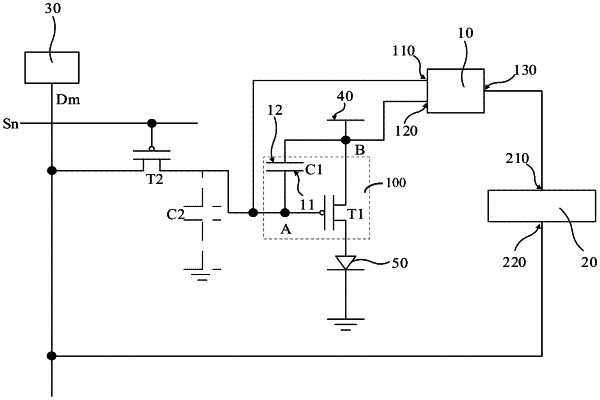
1. A compensation circuit, comprising:
at least one driving unit,
wherein each driving unit comprises a first response switch and a storage capacitor, wherein a first end of the first response switch is connected to a light emitting unit, and a second end of the first response switch is connected to a power supply;
wherein the storage capacitor has a first electrode plate and a second electrode plate opposite to the first electrode plate, wherein the first electrode plate is connected to a control end of the first response switch, the second electrode plate is connected to the second end of the first response switch, and the control end of the first response switch is configured to light up the light emitting unit in response to a data signal provided by a data line;
wherein the compensation circuit further comprises:
a subtractor provided with a first detection port, a second detection port and an output port; and
a controller provided with a receiving port and a feedback port;
wherein the first detection port is connected to the first electrode plate and the second detection port is connected to the second electrode plate;
wherein the receiving port of the controller is connected to the output port of the subtractor, and the feedback port of the controller is configured to provide a compensation signal to the data line; and
wherein the subtractor is configured to calculate a voltage difference between a first voltage data of the first detection port and a second voltage data of the second detection port, and transmit the voltage difference to the controller, and the controller is configured to provide the compensation signal to the data line based on the voltage difference.
|