| CPC F28F 9/185 (2013.01) [B23P 15/26 (2013.01); F28F 11/02 (2013.01)] | 5 Claims |

|
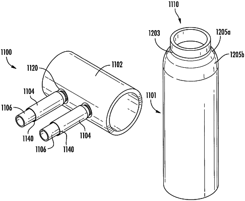
1. A method for connecting, repairing, or replacing a boiler tube of a boiler, the boiler having a header portion, the header portion having a header wall, the method comprising:
providing a tube transition fitting, comprising:
a first end and a second end opposite the first end;
a head adjacent the second end, the head having a constant wall thickness;
a body;
a beveled weld area adjacent the head, the beveled weld area being configured such that the tube transition fitting directly welded to the header portion using an external weld;
a first wall thickness; and
a second wall thickness;
wherein a transition between the first wall thickness and the second wall thickness defines a heat transition zone;
wherein a tube seat is formed on a surface connected to the body, the surface being adjacent a transition of the first wall thickness to the second wall thickness; and
fitting the boiler tube with the first end of the tube transition fitting adjacent the tube seat;
securing the boiler tube to the tube transition fitting using an external weld that does not require complete joint penetration, such that the weld does not contact an inner diameter of the boiler tube; and
securing the second end of the tube transition fitting to the header portion;
wherein the tube transition fitting is sizably compatible with the boiler tube, such that flow is consistent when transitioning between the boiler tube and the tube transition fitting;
wherein the head is seated within the header wall after welding, such that the head does not extend into the flow path of the header; and
wherein the tube transition fitting is secured to the header portion and the boiler tube via a purge-free process.
|