| CPC F23R 3/002 (2013.01) [F01D 25/12 (2013.01); F05D 2220/323 (2013.01); F05D 2240/35 (2013.01); F05D 2260/20 (2013.01); F23R 2900/03041 (2013.01)] | 12 Claims |

|
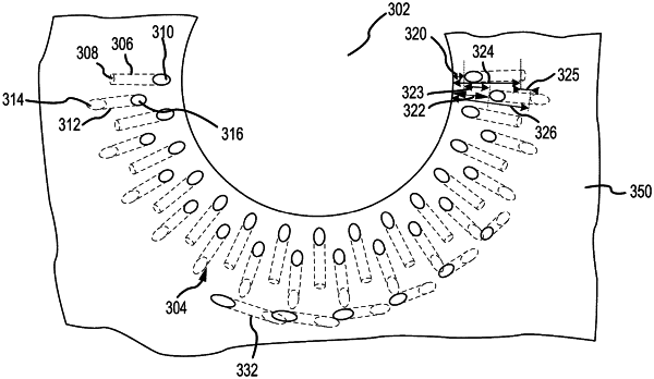
1. A gas turbine engine component, comprising:
a first surface and a second surface;
a dilution hole defined by the first surface and the second surface;
a grommet defined by the first surface and the second surface;
a plurality of first effusion holes located circumferentially about, at least, a portion of the dilution hole, wherein each first effusion hole of the plurality of first effusion holes has a first inlet defined entirely by a third surface of the grommet and a first outlet defined by the first surface; and
a plurality of second effusion holes interleaved circumferentially with the plurality of first effusion holes about the portion of the dilution hole, wherein each second effusion hole of the plurality of second effusion holes has a second inlet defined by the second surface and a second outlet defined by the first surface, and wherein the first outlet of each first effusion hole of the plurality of first effusion holes is located a first outlet distance from the dilution hole, wherein the second outlet of each second effusion hole of the plurality of second effusion holes is located a second outlet distance from the dilution hole, wherein the first outlet distance is less than the second outlet distance, wherein the first inlet of each of the first effusion hole of the plurality of first effusion holes is located a first inlet distance from the dilution hole, wherein the second inlet of each of the second effusion hole of the plurality of second effusion holes is located a second inlet distance from the dilution hole, wherein the first inlet distance is less than the second inlet distance, and wherein the first inlet distance is less than the second inlet distance by a same amount as a difference between the first outlet distance and the second outlet distance,
wherein each first effusion hole of the plurality of first effusion holes forms a first angle with respect to the first surface, wherein each second effusion hole of the plurality of second effusion holes forms a second angle with respect to the first surface,
wherein each first inlet of each first effusion hole of the plurality of first effusion holes is staggered between each second inlet of each second effusion hole of the plurality of second effusion holes in order to stagger each first outlet of each first effusion hole of the plurality of first effusion holes between each second outlet of each second effusion hole of the plurality of second effusion holes,
wherein the first inlet of each first effusion hole of the plurality of first effusion holes defined by the grommet is located nearer to the dilution hole than each second inlet of each second effusion hole of the plurality of second effusion holes defined by the second surface, and
wherein the first outlet of each first effusion hole of the plurality of first effusion holes and the second outlet of each second effusion hole of the plurality of second effusion holes are located on a same plane by the first surface, wherein the same plane defined by the first surface is perpendicular to a plane defined by the grommet and wherein the same plane defined by the first surface is parallel to a plane defined by the second surface.
|