|
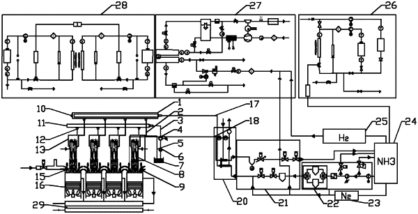
1. A liquid ammonia phase-change cooling type hybrid power thermal management system, comprising an injector, a liquid ammonia hydrogen supply system, a liquid ammonia common rail pipe, a fuel oil common rail pipe and an oil tank, wherein the liquid ammonia hydrogen supply system comprises a liquid ammonia storage tank, an ammonia pumping system, a flow dividing system and an ammonia inlet and outlet system, the fuel oil common rail pipe is respectively connected with the oil tank and a one-way oil inlet of the injector, the liquid ammonia common rail pipe is respectively connected with the ammonia inlet and outlet system and a one-way ammonia inlet of the injector, an ammonia inlet pipe and an ammonia return pipe are arranged in the ammonia inlet and outlet system, the ammonia pumping system comprises a liquid ammonia storage flow divider, a low-pressure pump and a high-pressure pump, the flow dividing system comprises a storage tank, an ammonia inlet control valve, a safety valve and an ammonia outlet control valve, an outlet of the liquid ammonia storage tank is sequentially connected with the low-pressure pump, the high-pressure pump, the liquid ammonia storage flow divider, the storage tank and the ammonia inlet control valve, the ammonia inlet control valve is connected with the liquid ammonia common rail pipe through the ammonia inlet pipe, an inlet of the liquid ammonia storage tank is sequentially connected with the ammonia outlet control valve and the safety valve, the safety valve is connected with the injector through the ammonia return pipe, and the liquid ammonia storage tank is respectively connected with a hydrogen storage tank and a nitrogen storage tank.
|
