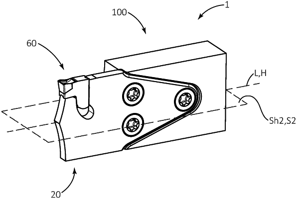
| CPC B23B 27/1611 (2013.01) [B23B 29/12 (2013.01); B23B 2205/12 (2013.01)] | 21 Claims |

|
1. A cutting blade (20, 20′, 20″) extending along a central blade axis (L) defining opposite forward and rearward blade directions (Fb, Rb);
the cutting blade (20, 20′, 20″) having first and second symmetry planes (S1, S2) perpendicular to one another, each containing the central blade axis (L);
the cutting blade (20, 20′, 20″) comprising:
opposite first and second blade side surfaces (22, 24) extending along, and on opposite sides of, the first symmetry plane (S1), a blade thickness (T1) being measured between the first and second blade side surfaces (22, 24) in a direction perpendicular to the first symmetry plane (S1);
a blade peripheral surface (30) connecting the first and second blade side surfaces (22, 24) and including:
opposite top and bottom blade surfaces (32, 34) extending along, and on opposite sides of, the second symmetry plane (S2), a blade height (H1) being measured between the top and bottom blade surfaces (32, 34) in a direction perpendicular to the central blade axis (L), the blade height (H1) being greater than the blade thickness (T1);
a forwardly facing forward blade surface (36) extending between the top and bottom blade surfaces (32, 34); and
a rearward blade end (42) opposite the forward blade surface (36);
a blade cutting portion (50) comprising a first insert seat (62) located at an intersection of the first blade side surface (22), the second blade side surface (24), the forward blade surface (36) and one of the top and bottom blade surfaces (32, 34); and
a blade fastening portion (70) extending from the blade cutting portion (50) in the rearward blade direction (Rb), wherein at the blade fastening portion (70);
the top blade surface (32) comprises a first peripheral blade abutment sub-surface (80a);
the bottom blade surface (34) comprises a second peripheral blade abutment sub-surface (80b);
the first and second blade side surfaces (22, 24) comprise, respectively, first and second blade side abutment sub-surfaces (82, 84); and
a first blade bore (72a) opens out to the first and second blade side abutment sub-surfaces (82, 84);
wherein:
the first insert seat (62) comprises an insert support surface (66) extending transversely to the second symmetry plane (S2) and directed against forces acting on a cutting insert seated therein during machining operations; and
the first and second peripheral blade abutment sub-surfaces (80a, 80b) converge in the rearward blade direction (Rb) at a first taper angle β1 and exhibit a mirror symmetric angle about the first and second symmetry planes (S1, S2).
|