| CPC B01D 29/6476 (2013.01) [B01D 29/014 (2013.01); B01D 29/23 (2013.01); B01D 2201/18 (2013.01); B01D 2221/06 (2013.01)] | 16 Claims |

|
1. A rotary tool comprising:
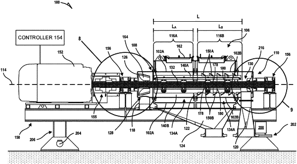
a center shaft having a longitudinal axis;
a plurality of longitudinal paddles coupled to the shaft, at least one paddle of the plurality of paddles having an inner edge and aligned radially relative to the longitudinal axis, wherein the at least one paddle has an elongate extent along the longitudinal axis with opposing lateral sides along the elongate extent; and
a flange having a triangular shape in a radial cross-section, the flange directly affixed to the inner edge of the at least one paddle and extending from the inner edge of the at least one paddle to an apex radially inward of the at least one paddle, wherein the flange is shaped as a wedge bar with a longitudinal extent and has two tapered faces extending from the apex, each of the two tapered faces positioned on a respective one of the opposing lateral sides of the at least one paddle.
|