| CPC A63B 21/078 (2013.01) [A63B 21/068 (2013.01); A63B 21/169 (2015.10); A63B 21/4035 (2015.10); A63B 23/0405 (2013.01); A63B 23/1218 (2013.01); A63B 71/0036 (2013.01); F16M 13/02 (2013.01); A63B 21/0628 (2015.10); A63B 21/0724 (2013.01); A63B 2023/0411 (2013.01); A63B 2210/00 (2013.01); A63B 2210/50 (2013.01)] | 20 Claims |

|
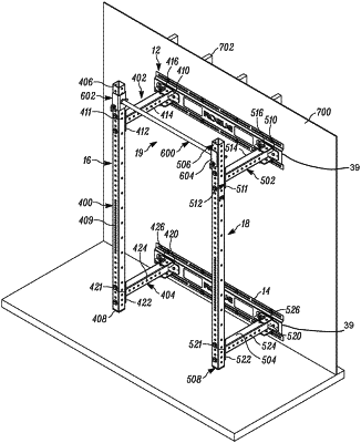
1. A weightlifting assembly, comprising:
a first wall mount bracket configured for mounting to a wall surface, comprising:
a first central panel having an inner surface configured to face the wall surface and an outer surface opposite the inner surface, the first central panel having a first mounting region and a second mounting region spaced from each other along the first central panel;
a first top wall mount panel located above the first central panel and configured to overlie the wall surface;
a first bottom wall mount panel located below the first central panel and configured to overlie the wall surface, wherein the first top and bottom wall mount panels are offset from the first central panel in a first direction perpendicular to the outer surface and the inner surface of the first central panel, wherein the first top wall mount panel has a first upper slot that is elongated along a length of the first top wall mount panel, and the first upper slot is configured to receive a first upper wall mount fastener therethrough to couple the first wall mount bracket to the wall surface, and wherein the first bottom wall mount panel has a first lower slot that is elongated along a length of the first bottom wall mount panel, and the first lower slot is configured to receive a first lower wall mount fastener therethrough to couple the first wall mount bracket to the wall surface; and
first offset panels respectively extending between the first central panel and the first top wall mount panel and between the first central panel and the first bottom wall mount panel, the first offset panels being respectively angled to each of the first central panel and the first top and bottom wall mount panels;
a second wall mount bracket configured for mounting to the wall surface at a location below the first wall mount bracket and spaced from the first wall mount bracket, comprising:
a second central panel having an inner surface configured to face the wall surface and an outer surface opposite the inner surface, the second central panel having a third mounting region and a fourth mounting region spaced from each other along the second central panel;
a second top wall mount panel located above the second central panel and configured to overlie the wall surface;
a second bottom wall mount panel located below the second central panel and configured to overlie the wall surface, wherein the second top and bottom wall mount panels are offset from the second central panel in the first direction, wherein the second top wall mount panel has a second upper slot that is elongated along a length of the second top wall mount panel, and the second upper slot is configured to receive a second upper wall mount fastener therethrough to couple the second wall mount bracket to the wall surface, and wherein the second bottom wall mount panel has a second lower slot that is elongated along a length of the second bottom wall mount panel, and the second lower slot is configured to receive a second lower wall mount fastener therethrough to couple the second wall mount bracket to the wall surface; and
second offset panels respectively extending between the second central panel and the second top wall mount panel and between the second central panel and the second bottom wall mount panel, the second offset panels being respectively angled to each of the second central panel and the second top and bottom wall mount panels; and
a weightlifting rack assembly connected to the first wall mount bracket and the second wall mount bracket, the weightlifting rack assembly comprising a first bracket connected to the first central panel of the first wall mount bracket at the first mounting region by a first fastener, a second bracket connected to the first central panel of the first wall mount bracket at the second mounting region by a second fastener, a third bracket connected to the second central panel of the second wall mount bracket at the third mounting region by a third fastener, and a fourth bracket connected to the second central panel of the second wall mount bracket at the fourth mounting region by a fourth fastener,
wherein the first top and bottom wall mount panels being offset from the first central panel is configured to create a first space between the inner surface of the first central panel and the wall surface, to provide clearance for the first and second fasteners, and
wherein the second top and bottom wall mount panels being offset from the second central panel is configured to create a second space between the inner surface of the second central panel and the wall surface, to provide clearance for the third and fourth fasteners, and
wherein the weightlifting rack assembly is foldable and comprises a first side rack assembly connected to the first bracket and the third bracket and a second side rack assembly connected to the second bracket and the fourth bracket, wherein the first, second, third, and fourth brackets are pivot brackets, and wherein the first side rack assembly is foldable by pivoting at the first and third brackets, and the second side rack assembly is foldable by pivoting at the second and fourth brackets.
|