| CPC H04B 1/0064 (2013.01) [H04B 1/50 (2013.01)] | 20 Claims |

|
1. A mobile device comprising:
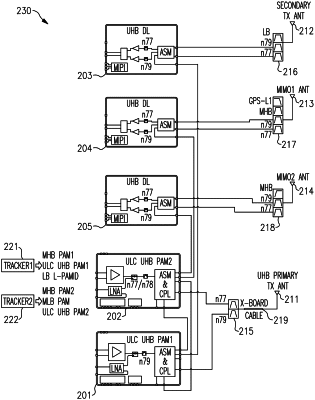
a diplexer including a first diplexer terminal, a second diplexer terminal, and a third diplexer terminal;
a cross-board cable;
a plurality of antennas including a first antenna connected to the third diplexer terminal of the diplexer through the cross-board cable, and a second antenna;
a transceiver; and
a radio frequency front-end system electrically coupled between the transceiver and the plurality of antennas, the radio frequency front-end system including a first ultrahigh band transmit/receive module including a first antenna switch and a first transmit/receive switch that is connected to the first antenna by way of both the first antenna switch and a first signal route to the first diplexer terminal of the diplexer, a second ultrahigh band transmit/receive module including a second antenna switch and a second transmit/receive switch that is connected to the first antenna by way of both the second antenna switch and a second signal route to the second diplexer terminal of the diplexer, a first ultrahigh band receive module including a third antenna switch connected to the second antenna, a second ultrahigh band receive module including a fourth antenna switch, a third ultrahigh band receive module including a fifth antenna switch separate from the fourth antenna switch, a third signal route between the first antenna switch and the third antenna switch through a first auxiliary input to the first ultrahigh band receive module, a fourth signal route between the second antenna switch and the fourth antenna switch through a second auxiliary input to the second ultrahigh band receive module, and a fifth signal route between the second antenna switch and the fifth antenna switch through a third auxiliary input to the third ultrahigh band receive module.
|