| CPC H02J 7/0068 (2013.01) [H02J 3/32 (2013.01); H02J 7/06 (2013.01); H02M 1/007 (2021.05); H02M 3/1582 (2013.01); H02M 3/33573 (2021.05); H02M 7/53871 (2013.01); H02J 2207/20 (2020.01)] | 8 Claims |

|
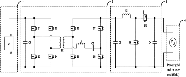
1. A battery charging and discharging circuit, comprising:
a battery module (1), configured to receive charging voltage or release discharging voltage;
a transformer circuit (2), connected with the battery module (1), the transformer circuit (2) is configured to convert a first charging voltage into a charging voltage or convert a discharging voltage into a first discharging voltage;
a buck-boost circuit (3), connected with the transformer circuit (2), the buck-boost circuit (3) is configured to convert a second charging voltage into the first charging voltage or convert the first discharging voltage into a second discharging voltage;
a power grid end or user end (4), connected with the buck-boost circuit (3), the power grid end or user end (4) is configured to generate the second charging voltage or receive the second discharging voltage;
the buck-boost circuit (3) comprises: a second inductor (L2), a ninth transistor (S9), a tenth transistor (S10), a third capacitor (C3) and a fourth capacitor (C4);
a first end of the third capacitor (C3) is connected to a first end of the transformer circuit (2);
a second end of the third capacitor (C3) is connected to a second end of the transformer circuit (2);
a first end of the second inductor (L2) is connected to the first end of the third capacitor (C3);
a second end of the second inductor (L2) is connected to a first end of the ninth transistor (S9);
a second end of the ninth transistor (S9) is connected to the second end of the third capacitor (C3);
a first end of the tenth transistor (S10) is connected to the second end of the second inductor (L2);
a second end of the tenth transistor (S10) is connected to a first end of the fourth capacitor (C4); and
a second end of the fourth capacitor (C4) is connected to the second end of the ninth transistor (S9).
|