| CPC G06F 30/28 (2020.01) [G01F 1/42 (2013.01); G01F 15/005 (2013.01)] | 9 Claims |

|
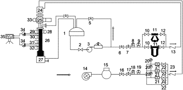
1. A device for early monitoring of gas intrusion based on pressure wave propagation, comprising:
a liquid storage tank;
a gas storage tank;
a simulated wellbore;
a computer;
a centrifugal pump;
a pressure-stabilizing water tank;
a mass flowmeter;
a screw air compressor;
a micro-orifice flowmeter;
a gas-liquid mixer;
a pressure-disturbing device;
a gas-liquid separator; and
an oscilloscope;
wherein a lower end of the liquid storage tank is connected to an inlet end of the pressure-stabilizing water tank through a first liquid-injection pipeline and the centrifugal pump;
an outlet end of the pressure-stabilizing water tank is connected to a liquid inlet of the gas-liquid mixer through a second liquid-injection pipeline and the mass flowmeter;
a first end of the gas storage tank is connected to the screw air compressor and a second end of the gas storage tank is connected to a gas inlet of the gas-liquid mixer through a gas-injection pipeline and the micro-orifice flowmeter;
the gas-liquid mixer is provided at an upper end of the simulated wellbore;
the pressure-disturbing device is connected to a lower side of the gas-liquid mixer;
a plurality of pressure sensors are provided at a middle of the simulated wellbore, and connected to the computer through a wire and the oscilloscope;
the gas-liquid separator is connected to a lower end of the simulated wellbore, and a liquid outlet of the gas-liquid separator is in pipeline connection with the liquid storage tank for recycling; and
the pressure-disturbing device comprises:
a pressure wave generator;
a pressure wave propagation unit; and
a disturbance tube;
wherein the pressure wave generator is provided with one or more pistons;
a lower outlet of each of the one or more pistons is connected to a collection chamber;
an outlet end of the collection chamber communicates with the pressure wave propagation unit;
an outer wall of the disturbance tube is provided with a plurality of openings;
the plurality of openings are each provided with a rubber membrane;
an outer end of the pressure wave propagation unit is connected to the disturbance tube; and
the rubber membrane is configured to collect and concentrate pressure waves for propagation.
|