|
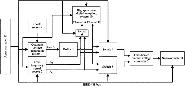
1. A system for verifying alternating current (AC)/direct current (DC) conversion of an ultralow-frequency voltage based on a quantum technology, wherein the system comprises a quantum voltage generation system (1), a low-frequency signal source (2), a follower (3), a first switch (4), a second switch (5), a third switch (6), a double-heater-strip thermoelectric converter (7), a nanovoltmeter (8), a clock source (9), a high-precision digital sampling system (10), and an upper computer (11), wherein the quantum voltage generation system (1) is separately connected to the first switch (4), the second switch (5), and a channel B of the high-precision digital sampling system (10) by using the follower (3), the low-frequency signal source (2) is connected to the first switch (4), the second switch (5), and the third switch (6), the third switch (6) is connected to a channel A of the high-precision digital sampling system (10), the first switch (4) and the second switch (5) are connected to the double-heater-strip thermoelectric converter (7), the double-heater-strip thermoelectric converter (7) is connected to the nanovoltmeter (8), the clock source (9) is connected to the quantum voltage generation system (1), the low-frequency signal source (2), and the high-precision digital sampling system (10), and the upper computer (11) is connected to the quantum voltage generation system (1), the low-frequency signal source (2), the first switch (4), the second switch (5), the third switch (6), the nanovoltmeter (8), and the high-precision digital sampling system (10); the quantum voltage generation system (1) provides an AC quantum voltage US and a DC quantum voltage UD; the low-frequency signal source (2) provides two equal-amplitude and orthogonal low-frequency voltage signals UA1 and UA2; the follower (3) is configured to improve a load capacity of a quantum voltage system; the first switch (4) and the second switch (5) are used to control switching between a low-frequency voltage signal and DC quantum voltage at the input terminal of the dual-heater thermal voltage converter (7); the third switch (6) is used to control switching between the two low-frequency voltage signals UA1 and UA2 connected to the channel A of the high-precision digital sampling system (10); the double-heater-strip thermoelectric converter (7) is configured to realize equivalent conversion between the low-frequency voltage signals UA1 and UA2 and the DC quantum voltage; the nanovoltmeter (8) is configured to read thermoelectric potentials output by the double-heater-strip thermoelectric converter (7) in AC and DC states; the clock source (9) provides a synchronous clock signal to realize synchronous output of the quantum voltage generation system (1) and the low-frequency signal source (2), as well as synchronous measurement of the high-precision digital sampling system (10); the high-precision digital sampling system (10) is configured to precisely measure a difference between the AC quantum voltage and the low-frequency voltage signal; and the upper computer (11) is configured to control the whole system to realize automatic measurement.
|
