| CPC F17C 13/083 (2013.01) [B67D 7/04 (2013.01); B67D 7/36 (2013.01); B67D 7/62 (2013.01); B67D 7/845 (2013.01); F17C 6/00 (2013.01); F17C 9/00 (2013.01); F17C 2201/0104 (2013.01); F17C 2201/0119 (2013.01); F17C 2201/035 (2013.01); F17C 2201/054 (2013.01); F17C 2205/0107 (2013.01); F17C 2205/0126 (2013.01); F17C 2205/0157 (2013.01); F17C 2205/0323 (2013.01); F17C 2221/012 (2013.01); F17C 2221/013 (2013.01); F17C 2221/033 (2013.01); F17C 2221/035 (2013.01); F17C 2223/0123 (2013.01); F17C 2223/0153 (2013.01); F17C 2223/0161 (2013.01); F17C 2223/033 (2013.01); F17C 2223/035 (2013.01); F17C 2225/0161 (2013.01); F17C 2225/033 (2013.01); F17C 2225/044 (2013.01); F17C 2227/0341 (2013.01); F17C 2265/065 (2013.01); F17C 2270/0168 (2013.01); F17C 2270/0173 (2013.01); Y02E 60/32 (2013.01)] | 26 Claims |

|
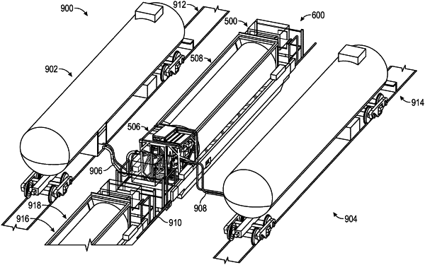
1. A fluid commodity transfer structure comprising:
a base member having a top surface, a bottom surface, and at least one intermodal footprint, the base member configured for intermodal transport, wherein the top surface of the base member is configured to receive at least one receptacle disposed on the top side of the base member;
a casing coupled to the top surface at a first end of the base member and abutting the at least one intermodal footprint, wherein the casing and the top surface of the base member are of a unitary construction forming a single structure;
a fluid commodity transfer system disposed on the top surface of the base member within the casing, the fluid commodity transfer system comprising:
a first side comprising a first outlet, a first inlet, and a first pump;
a second side that is opposite the first side, the second side comprising a second outlet, a second inlet, and a second pump; and
a third side comprising a third inlet, the third side facing the at least one receptacle;
a barrier member coupled to a distal end of the base member opposite from the casing, the barrier member configured to:
abut the at least one receptacle; and
secure the at least one receptacle to the base member between the barrier member and the casing; and
a conduit configured to operably couple the fluid commodity transfer system to the at least one receptacle, wherein the conduit is configured to couple the fluid commodity transfer system to a receptacle of another fluid commodity transfer structure to facilitate the fluid commodity transfer system transporting fluid to or from the receptacle of the another fluid commodity transfer structure.
|