| CPC F16H 61/662 (2013.01) [F16H 61/32 (2013.01); F16H 2061/2892 (2013.01); F16H 2061/66295 (2013.01)] | 7 Claims |

|
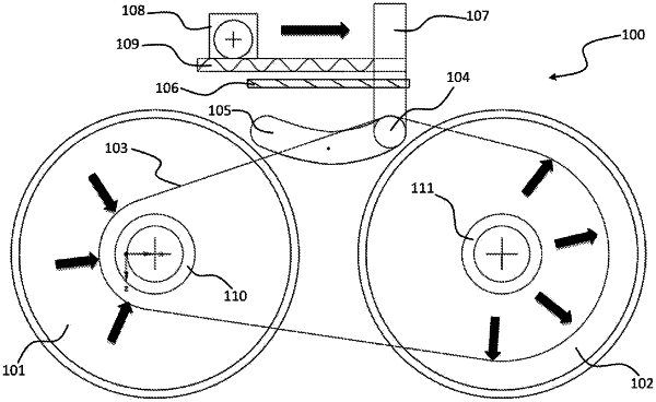
1. A control mechanism for transmitting a power from an input part to an output part uninterruptedly, non-gradually and continuously by means of a Continuous Variable Transmission (SDA, CVT) systems, it comprises;
an input pulley (101) that transmits athe torque from the input to the output part over a transmission element (103),
an output pulley (102) that transmits the torque transmitted by the transmission element (103) to a related machine element over an output shaft,
the transmission element (103) that transmits torque from the input pulley (101) to the output pulley (102), characterized by comprising;
a control arm (107) providing gear shifting in the continuous variable transmission system,
a drive element (108) providing determining the gear ratio by thrusting the control arm (107) back and forth,
a control roller (104) which is a protrusion of the control arm (107), and which is thrusted by the drive element (108) to control a position of the transmission element (103),
a control arm trajectory (105) thrusted by the drive element (108) to determine a cycle ratio of the continuously variable transmission,
a control arm bearing (106) providing bearing of the control arm (107) from top,
a drive arm (109) providing a movement of the control arm (107) through converting a rotation movement from the drive element into a thrust movement
an input pressure spring (110) providing a non-slidable rotation of the transmission element by pressing a plurality of contact points of the transmission element (103) between the input pulley (101),
an output pressure spring (111) enables the non-slidable rotation of the transmission element by pressing the plurality of contact points of the transmission element (103) between the output pulleys (102).
|