| CPC F04D 29/669 (2013.01) [F04D 1/00 (2013.01); F04D 9/06 (2013.01); F04D 15/0005 (2013.01); F04D 27/00 (2013.01); F04D 29/086 (2013.01); F04D 29/28 (2013.01)] | 5 Claims |

|
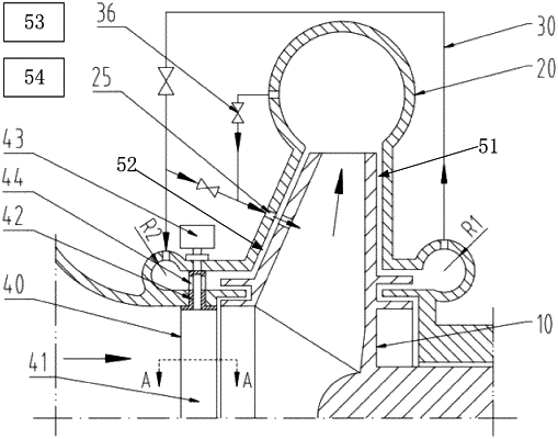
1. An adjusting apparatus for improving an anti-cavitation effect of a water pump, comprising a centrifugal impeller (10), a volute (20), an adjusting device (30), a jet device (40), a pressure and/or flow monitoring device (53), and a controller (54), wherein the centrifugal impeller is mounted in the volute, the centrifugal impeller comprises a front disc (11), a rear disc (12), blades (13), a rotating shaft (14), a rear side labyrinth seal (15), and a front side labyrinth seal (16), the blades (13) are distributed in a circumferential direction and are connected between the front disc and the rear disc, a middle position of the rear disc is provided with the rotating shaft, the rotating shaft is connected to a motor through a bearing box and a coupling, an outer side of the rear disc is provided with the rear side labyrinth seal (15), and an outer side of the front disc is provided with the front side labyrinth seal (16); the volute comprises a first sealing portion (21), a first pressure adjusting cavity (22), a second sealing portion (23), and a second pressure adjusting cavity (24), a position of the first sealing portion corresponds to the rear side labyrinth seal and constitutes a first labyrinth seal, a position of the second sealing portion corresponds to the front side labyrinth seal and constitutes a second labyrinth seal, and the pressure and/or flow monitoring device is used for monitoring pressure and/or flow at an inlet and an outlet of the water pump, wherein the position of the first sealing portion is provided with the first pressure adjusting cavity, the first pressure adjusting cavity has a first pressure, and the first pressure adjusting cavity is in communication with a rear side cavity of the rear disc (51) through the first labyrinth seal, the position of the second sealing portion is provided with the second pressure adjusting cavity, the second pressure adjusting cavity has a second pressure, and the second pressure adjusting cavity is in communication with a front side cavity of the front disc (52) through the second labyrinth seal; and the adjusting device comprises a first pipeline (31), the second pressure adjusting cavity is in communication with the first pressure adjusting cavity through the first pipeline, the jet device is mounted in an inlet pipe of the volute, the jet device is in communication with the second pressure adjusting cavity, and a cross sectional area of the first pressure adjusting cavity (22) is greater than a cross sectional area of the second pressure adjusting cavity (24); wherein
the first pressure adjusting cavity (22) has a radius R1, the second pressure adjusting cavity (24) has a radius R2, and R1 is 1.3 to 2 times of R2;
the adjusting device (30) comprises the first pipeline (31), a second pipeline (32), a third pipeline (33), a first regulation and control valve (34), a second regulation and control valve (35), and a third regulation and control valve (36), the first pipeline is provided with the first regulation and control valve, a first through-hole (25) is formed on a front side wall of the volute (20) at a position corresponding to the front disc (11), a second through-hole is formed on a pumping chamber of the volute, the pumping chamber is located on a radial outer side of the centrifugal impeller, two ends of the second pipeline are respectively in communication with the second through-hole and the first through-hole, two ends of the third pipeline are respectively in communication with the first pipeline and the first through-hole, the third pipeline is provided with the second regulation and control valve, an upstream end of the third pipeline (33) is connected between the first regulation and control valve and the second pressure adjusting cavity, and the second pipeline is provided with the third regulation and control valve;
and a backflow hole (17) is formed on the front disc (11), a position of the backflow hole corresponds to the position of the first through-hole (25), and the quantity of the backflow holes is one or more which are distributed in the circumferential direction.
|