| CPC F02C 3/30 (2013.01) [F05D 2220/32 (2013.01); F05D 2240/35 (2013.01); F05D 2270/08 (2013.01)] | 11 Claims |

|
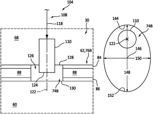
1. An assembly for a turbine engine, comprising:
a housing comprising an air plenum;
a combustor disposed within the air plenum, the combustor including a combustor wall and a combustion chamber, the combustor wall disposed between the combustion chamber and the air plenum, and the combustor wall comprising a quench aperture that extends through the combustor wall from the air plenum to the combustion chamber; and
a steam injector projecting partially into or through the quench aperture, the steam injector non-coaxial with the quench aperture.
|
|
9. An assembly for a turbine engine, comprising:
a housing comprising an air plenum;
a combustor disposed within the air plenum, the combustor including a combustor wall and a combustion chamber, the combustor wall disposed between the combustion chamber and the air plenum, and the combustor wall comprising a quench aperture that extends through the combustor wall from the air plenum to the combustion chamber; and
a steam injector projecting partially into or through the quench aperture;
wherein the quench aperture extends laterally between an upstream side and a downstream side relative to a flow of combustion products within the combustion chamber; and
wherein the steam injector is arranged closer to the upstream side than the downstream side.
|