| CPC F02C 3/30 (2013.01) [F05D 2220/323 (2013.01); F05D 2240/35 (2013.01)] | 11 Claims |

|
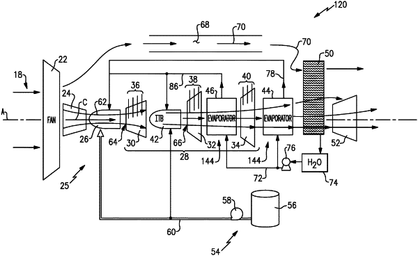
1. A turbine engine assembly comprising:
a compressor section where a core airflow is compressed;
a combustor section where the compressed core airflow from the compressor section is mixed with fuel and ignited to generate an exhaust gas flow;
a turbine section including at least two turbine stages through which the exhaust gas flow expands to generate a mechanical power output;
an inter-turbine burner disposed between the at least two turbine stages, wherein in the inter-turbine burner an additional amount of fuel is mixed with the exhaust gas flow to generate a reheated gas flow;
a condenser where water is extracted from the reheated gas flow exhausted from the turbine section; and
an evaporator system disposed between a turbine stage of the at least two turbine stages and the condenser, the evaporator system configured for generating a steam flow from at least a portion of water extracted by the condenser for injection into the core airflow, wherein the evaporator system includes a first evaporator disposed between a first turbine stage and a second turbine stage of the at least two turbine stages and a second evaporator disposed between the turbine section and the condenser.
|