| CPC F01D 5/286 (2013.01) [F03D 1/0675 (2013.01)] | 20 Claims |

|
1. A method of forming an erosion shield for use with a turbine blade, the method comprising:
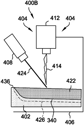
depositing a layer of filler material using a directed energy deposition (DED) system on a build platform of the DED system, the layer of filler material defining an upper surface;
depositing a layer of erosion-resistant material across the upper surface of the layer of filler material using the DED system, an interface being defined between the layer of filler material and the layer of erosion-resistant material and having a shape of the upper surface; and
machining the layer of filler material to remove the erosion shield from the build platform, the erosion shield extending a length between a base end and a nose, the erosion shield having the layer of erosion-resistant material, the machined layer of filler material, and the interface defined therebetween, an inner surface of the erosion shield being defined by the machined layer of filler material that is sized and shaped for attaching to a leading edge of the turbine blade, wherein the layer of filler material is machined along a cut line having a shape that complements the shape of the upper surface of the layer of filler material such that each of the interface and the inner surface extend the length of the erosion shield.
|