| CPC E04F 15/02044 (2013.01) [E04F 13/0801 (2013.01); E04F 15/183 (2013.01); F16B 5/002 (2013.01); F16B 5/0088 (2013.01); F16B 5/0621 (2013.01); E04F 2015/02094 (2013.01); E04F 2201/0523 (2013.01)] | 17 Claims |

|
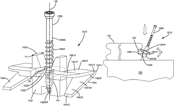
1. A method of using a fastener unit comprising:
providing a fastener unit including a spacer block, a grip element extending from front and rear surfaces of the spacer block, and a resilient compression element joined with the spacer block, the resilient compression element comprising a moveable wing disposed at an angle to a fixed wing extending from the front surface and extending rearwardly along a lateral side of the spacer block, the moveable wing comprising a first end joined with the fixed wing and a second end, opposite the first end, comprising a terminal edge of the moveable wing, the terminal edge being disposed a first distance under the fixed wing;
inserting the second end of the moveable wing into a first groove of a first board so that the terminal edge is adjacent a lower surface of the first groove;
pressing the moveable wing against the lower surface of the first groove while pivoting the fastener unit to compress the moveable wing toward the fixed wing; and
engaging an upper surface of the grip element against an upper surface of the first groove above the lower surface of the first groove,
wherein the moveable wing resiliently presses against the lower surface of the first groove and the upper surface of the grip element presses against the upper surface of the first groove, thereby holding the spacer block adjacent the first groove of the first board,
wherein the terminal edge moves closer to the fixed wing during the pressing so that the terminal edge is disposed a second distance under the fixed wing, the second distance being less than the first distance,
wherein the moveable wing extends beyond both the front surface and the rear surface of the spacer block, forward and rearward of the spacer block, while extending downward toward the terminal edge.
|