| CPC B61K 9/08 (2013.01) [B61B 13/08 (2013.01); G01R 1/16 (2013.01); G01R 29/0807 (2013.01); G01R 33/038 (2013.01)] | 7 Claims |

|
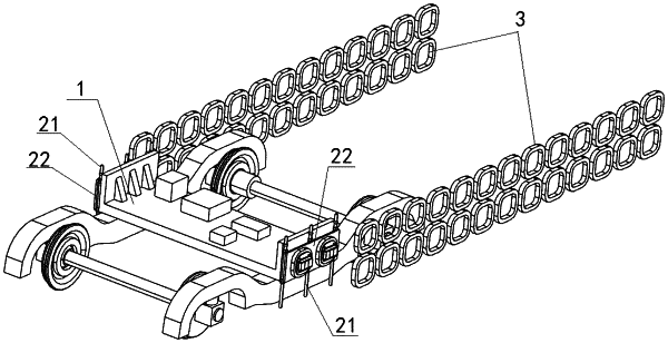
1. A fault detection device for a superconducting electrodynamic magnetic levitation (maglev) track, comprising:
a frame system; and
a detection system;
wherein the frame system is provided between two sidewall discrete figure-8-shaped coil tracks; and a signal processing device is provided on a top of the frame system;
two sides of the frame system are each provided with the detection system; the detection system comprises a lifting device and a clamping device; the lifting device is configured to adjust a vertical height of the clamping device; the clamping device is provided at an outer side of the lifting device; the clamping device is provided with a first connection portion and a second connection portion; the second connection portion is provided at an outer periphery of the first connection portion; the first connection portion is configured for connection with a permanent magnet array, and the second connection portion is configured for connection with a receiving coil; and the receiving coil is electrically connected to the signal processing device;
the permanent magnet array comprises a first Halbach permanent magnet and a second Halbach permanent magnet disposed side by side, and each of the first Halbach permanent magnet and the second Halbach permanent magnet has at least two predetermined magnetization acute angles different from each other, wherein a 90° magnetization angle is preset between the at least two predetermined magnetization acute angles;
each of the first Halbach permanent magnet and the second Halbach permanent magnet is cross-shaped; a width of the first Halbach permanent magnet is defined as a first width, and a width of the second Halbach permanent magnet is defined as a second width; a first main magnetic pole is provided in the first Halbach permanent magnet, and a second main magnetic pole is provided in the second Halbach permanent magnet; a horizontal distance from a center of the first main magnetic pole to a center of the second main magnetic pole is a defined as a target polar distance; the target polar distance, the first width and the second width are adapted to be controlled by means of a predetermined polar distance model; the predetermined polar distance model is expressed by:
 wherein b1 represents the first width; k1 represents a first predetermined polar arc coefficient; L represents the target polar distance; b2 represents the second width; and k2 represents a second predetermined polar arc coefficient;
the first connection portion comprises a mounting substrate; the mounting substrate is provided with a slot; and the permanent magnet array is fixedly connected in the slot; and
the second connection portion is a mounting base; the receiving coil is sleevedly provided on an outer wall of the mounting base; the mounting substrate is arranged at a center of the mounting base, and a center of gravity of the mounting substrate is configured to be coincided with that of the mounting base; and a position of the permanent magnet array relative to the receiving coil is fixed.
|