| CPC B60L 50/64 (2019.02) [B60L 3/04 (2013.01); H02H 3/087 (2013.01)] | 11 Claims |

|
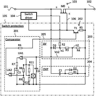
1. An electronic circuit breaker with self-triggering protection for a vehicle, comprising:
an input configured to be connected to an electric direct current (DC) power supply;
an output configured to be connected to a load;
a switch connected between the input and the output, wherein said switch is controlled via a switch control line between an “ON”-state and an “OFF”-state;
a switch driver connected to the switch control line, said switch driver is configured to control the switch; and
a switch protection connected between the input and the output and parallel with the switch, said switch protection is further connected to the switch control line, wherein the switch protection comprises:
an over-voltage protection branch extending from the input to the output;
a voltage detection branch extending from the input to the output and configured to output a first electric potential indicative of the electrical potential difference between the input and the output;
a comparator circuit configured to compare the first electrical potential with a first threshold voltage, said first threshold voltage is indicative of an over-current level flowing through the switch, which over-current causes a voltage drop over the switch, said comparator circuit outputs a switch disable signal via a switch disable line upon detecting that the first electrical potential is above the first threshold voltage; and
a gate controller connected to the switch disable line and configured to disable the switch by connecting the switch control line to a potential which causes the switch to enter the “OFF”-state.
|