| CPC B41F 31/24 (2013.01) [B32B 1/00 (2013.01); B32B 5/18 (2013.01); B32B 7/022 (2019.01); B32B 25/042 (2013.01); B32B 25/045 (2013.01); B32B 25/20 (2013.01); B41F 16/0086 (2013.01); B41F 17/001 (2013.01); B41F 17/34 (2013.01); B32B 2307/536 (2013.01); B41M 1/40 (2013.01)] | 9 Claims |

|
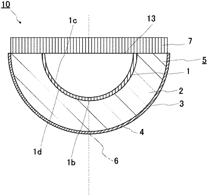
1. A printing pad comprising:
a printing surface to be pushed against a printing original plate and a surface to be printed, the printing original plate having ink placed on the printing original plate, the surface to be printed being an object to be printed;
an inner layer disposed inside the printing pad; and
an outer layer provided in contact with a surface of the inner layer that is closer to where the printing surface is disposed than is an opposite surface of the inner layer, wherein the inner layer has a higher hardness than the outer layer,
the outer layer having the printing surface on an outside surface of the outer layer, and being formed such that the printing surface is brought into close contact with the surface to be printed to conform to the surface to be printed when the printing surface is pushed against the surface to be printed,
the inner layer having a cavity provided in the inner layer.
|