| CPC B01L 3/502715 (2013.01) [B01L 9/527 (2013.01); G01N 21/05 (2013.01); B01L 2200/0689 (2013.01); B01L 2300/0627 (2013.01); B01L 2300/069 (2013.01); B01L 2300/0887 (2013.01); B01L 2300/165 (2013.01)] | 26 Claims |

|
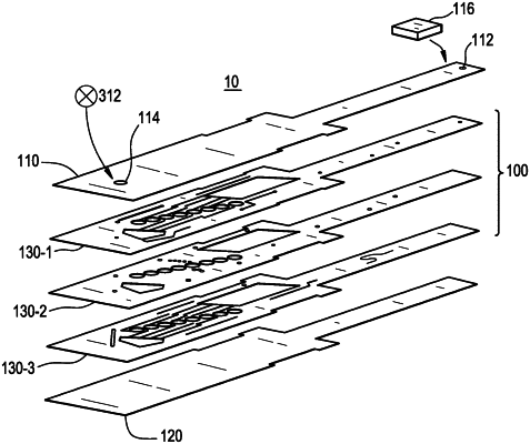
1. A microfluidic system comprising:
a body structure comprising
(a) a first outer layer forming a first side of the body structure;
(b) a second outer layer forming a second side of the body structure;
(c) a microfluidic assembly comprising at least a first substrate layer and disposed between the first outer layer and the second outer layer;
(d) a first port disposed through the first outer layer and in fluid communication with the microfluidic assembly; and
(e) a second port disposed through either the first outer layer or the second outer layer and adapted to be attached to a vacuum source such that a fluid flow path is defined from the first port to the second port through the microfluidic assembly;
wherein the microfluidic assembly comprises:
(i) a reaction chamber manifold and a waste reservoir; and
(ii) two or more parallel fluid flow paths between the reaction chamber manifold and the waste reservoir, wherein each fluid flow path comprises at least one reaction chamber comprising a dried film, a paper, or a gel comprising one or more test reagents, and wherein the at least one reaction chamber is adapted for an optical measurement;
wherein the reaction chamber manifold is on a sample supply inlet of each of the two or more fluid flow paths;
wherein the reaction chamber manifold on the sample supply inlet of each of the two or more fluid flow paths has a volume greater than the volume of the at least one reaction chamber; and
wherein the waste reservoir has a volume greater than the volume of the at least one reaction chamber.
|