US 12,128,357 B2
Catalytically active particulate filter
Jan Schoenhaber, Darmstadt (DE); Naina Deibel, Pfungstadt (DE); Martin Roesch, Rodgau (DE); Stephanie Spiess, Darmstadt (DE); Joerg-Michael Richter, Frankfurt (DE); and Susanne Kunert, Seeheim-Jugenheim (DE)
Assigned to UMICORE AG & CO. KG, Hanau-Wolfgang (DE)
Filed by UMICORE AG & CO. KG, Hanau-Wolfgang (DE)
Filed on Mar. 2, 2023, as Appl. No. 18/177,490.
Application 18/177,490 is a continuation of application No. 16/954,323, granted, now 11,628,400, previously published as PCT/EP2018/084898, filed on Dec. 14, 2018.
Claims priority of application No. 17208615 (EP), filed on Dec. 19, 2017.
Prior Publication US 2023/0285899 A1, Sep. 14, 2023
This patent is subject to a terminal disclaimer.
Int. Cl. B01D 53/94 (2006.01); B01J 21/06 (2006.01); B01J 23/10 (2006.01); B01J 23/46 (2006.01); B01J 23/63 (2006.01); B01J 35/00 (2006.01); B01J 35/56 (2024.01); F01N 3/035 (2006.01); F01N 3/10 (2006.01); F01N 3/28 (2006.01)
CPC B01D 53/945 (2013.01) [B01D 53/9468 (2013.01); B01J 21/066 (2013.01); B01J 23/10 (2013.01); B01J 23/464 (2013.01); B01J 23/63 (2013.01); B01J 35/19 (2024.01); B01J 35/56 (2024.01); F01N 3/035 (2013.01); F01N 3/101 (2013.01); F01N 3/28 (2013.01); F01N 3/2825 (2013.01); B01D 2255/1021 (2013.01); B01D 2255/1023 (2013.01); B01D 2255/1025 (2013.01); B01D 2255/2061 (2013.01); B01D 2255/2063 (2013.01); B01D 2255/2065 (2013.01); B01D 2255/2066 (2013.01); B01D 2255/20715 (2013.01); B01D 2255/2092 (2013.01); B01D 2255/407 (2013.01); B01D 2255/9022 (2013.01); B01D 2255/908 (2013.01); B01D 2255/9155 (2013.01); B01D 2258/014 (2013.01); F01N 2330/06 (2013.01); F01N 2330/30 (2013.01); F01N 2370/02 (2013.01); F01N 2510/06 (2013.01); F01N 2510/0684 (2013.01)] 23 Claims
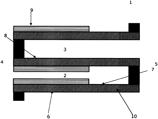
OG exemplary drawing
 
1. A particulate filter for removing particles, carbon monoxide, hydrocarbons and nitrogen oxides from exhaust gas of a combustion engine fueled by a stoichiometric air-fuel mixture, the particulate filter comprises a wall-flow filter of length L and two different coatings Y and Z, wherein the wall-flow filter comprises channels E and channels A that extend in parallel between a first end and a second end of the wall-flow filter and are separated by porous walls which form surfaces OF and surfaces OA, respectively, and wherein the channels E are closed at the second end and the channels A are closed at the first end, wherein the coating Y is located in the channels E on the surfaces OF and extends from the first end of the wall-flow filter over a length (Ly) of 51 to 90% of the length L with a thickness between 5-250 μm and the coating Z is located in the porous walls and extends from the second end of the wall-flow filter over a length (Lz) of 60 to 100% of the length L such that from 10% to 49% of the porous walls of channels E are exposed as to enable exhaust gas contact with coating Y followed by exhaust gas flow to the exposed porous walls in channels E and into contact with coating Z, and wherein length Ly plus length Lz is 110 to 180% of length L and coating Y has a coating load of from 33 to 125 g/l, based on the volume of the wall flow filter, and coating Z has a coating load of from 33 to 125 g/l, based on the volume of the wall flow filter.