| CPC A61M 25/007 (2013.01) [A61M 25/0043 (2013.01); A61M 25/09041 (2013.01); A61M 25/10 (2013.01); A61B 2017/00243 (2013.01); A61M 25/0102 (2013.01); A61M 25/0108 (2013.01); A61M 2025/09133 (2013.01); A61M 2025/1093 (2013.01); A61M 2210/125 (2013.01)] | 4 Claims |

|
1. A method of venting desired portions of a patient's heart, including the left or right ventricle or the left or right atrium, comprising:
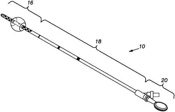
providing a catheter having:
an elongate, flexible tube that defines a first passageway, the tube having a distal end, a central portion, and a proximal end, the tube being made of a material selected from the group consisting of latex, vinyl, and silicone;
a generally rounded tip included as part of the distal end that defines the forwardmost end of the tube;
a single inflatable balloon included as part of the distal end and surrounding at least a portion of the tube, the balloon when inflated being smooth-sided and capable of engaging the patient's mitral valve, aortic valve, pulmonary valve or tricuspid valve and preventing retraction of the distal end from the left ventricle, right atrium or other desired location in the heart;
wherein the balloon when inflated is defined by a pair of end walls that are spaced from each other approximately 0.95 inch and an oval center portion that has a diameter of approximately 1.0 inch;
a plurality of first openings in the distal end that establish fluid communication with the first passageway, the first openings being disposed between the generally rounded tip and that portion of the balloon closest to the generally rounded tip;
a plurality of second openings in the distal end that establish fluid communication with the first passageway, the second openings being disposed adjacent the balloon on the proximal side thereof;
wherein 10 first openings and 10 second openings are provided in the distal end, each opening being approximately 2.5 mm in diameter, the first and second openings being provided in pairs that open through the tube on opposite sides of the tube, each pair of the first and second openings being oriented approximately 90 degrees relative to adjacent pairs of the first and second openings as measured along a centerline extending through the center of the tube;
the size, shape, and number of first and second openings being such that 50 cc per minute or more of air, blood, other fluid or debris can be withdrawn through the tube under suction;
wherein the step of providing a catheter includes the step of providing circumferentially extending retainer bands that engage each side of the balloon and hold it to the tube, the retainer bands being spaced from the first and second openings closest to the balloon by approximately 0.030 inch;
the distal end with the balloon collapsed and the central portion each having an outer diameter, the outer diameter of the distal end and the central portion being such that they are capable of being fed through the patient's inferior or superior vena cava, the right pulmonary vein or any desired location in the heart for the application of the device and the distal end is capable of extending into the patient's left ventricle, right atrium or other desired location in the heart;
a second passageway that extends along at least a portion of the length of the tube, the second passageway being in fluid communication with the balloon, the tube including a wall and the second passageway is formed as part of the wall;
a branch tube included as part of the proximal end, the branch tube projecting from the side of the elongate, flexible tube, the branch tube being in fluid communication with the second passageway; and
a plurality of visual markers disposed on the outside of the tube, the markers being evenly spaced at predetermined intervals along the length of the tube;
providing an elongate stiffening member of a size and shape that permits it to be inserted into and removed from the first passageway;
inserting the elongate stiffening member in the first passageway;
inserting the distal end into a desired portion of the patient's heart by passing the elongate tube through the patient's inferior or superior vena cava, the right pulmonary vein or any desired location in the heart for the application of the device;
removing the elongate stiffening member from the first passageway after the distal end has been inserted into a desired portion of the patient's heart;
inflating the balloon by pumping fluid into the second passageway through the branch tube until the balloon reaches a size to engage the mitral valve, aortic valve, pulmonary valve or the tricuspid valve so as to prevent retraction of the distal end from the desired portion of the patient's heart; and
removing blood, other fluid, debris and/or air from the desired portion of the patient's heart by withdrawing the blood, other fluid, debris and/or air through the first openings in the distal end and the first passageway.
|