| CPC A61M 1/80 (2021.05) [A61M 1/73 (2021.05); A61M 1/743 (2021.05); A61M 1/79 (2021.05); A61M 1/915 (2021.05); A61M 1/962 (2021.05); B29C 65/4845 (2013.01); H05K 1/0274 (2013.01); H05K 1/028 (2013.01); A61M 1/92 (2021.05); A61M 2205/3313 (2013.01); A61M 2205/6063 (2013.01); A61M 2205/70 (2013.01); A61M 2205/8206 (2013.01); A61M 2207/00 (2013.01)] | 14 Claims |

|
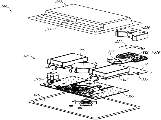
1. A method of inspection of an electronics unit for use in a negative pressure wound dressing apparatus, the method comprising:
applying a coating material to a portion of the electronics unit, wherein the coating material comprises a material that will fluoresce when exposed to UV light and the electronics unit comprises:
a negative pressure source;
an exhaust mechanism comprising a casing comprising an elongate portion comprising a first surface and an opposite second surface, wherein the first surface of the elongate portion is configured to extend at least partially across a surface of the negative pressure source; and
a flexible circuit board, wherein the second surface of the elongate portion of the casing is configured to extend at least partially across a surface of the flexible circuit board;
wherein the exhaust mechanism comprises a translucent or transparent material or a material that allows transmission of UV light; and
wherein the coating material is positioned between the translucent or transparent material or the material that allows transmission of UV light and the flexible circuit board; and
positioning the coated electronics unit under UV light to cause the coating material to fluoresce.
|