| CPC A01C 17/003 (2013.01) [A01M 9/0061 (2013.01); A01M 9/0069 (2013.01); B64C 39/024 (2013.01); B64D 1/16 (2013.01); B64U 10/13 (2023.01); B64U 30/20 (2023.01); B64U 2101/60 (2023.01)] | 13 Claims |

|
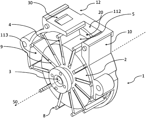
1. A dispenser unit for dispensing biological material, said dispenser unit comprising:
a rotary arrangement with a drive shaft and a plurality of protruding vanes, extending radially away from the drive shaft,
a housing for encasing at least a part of the rotary arrangement to form chambers configured to contain biological material between respective neighbouring vanes and an inner wall of the housing, wherein the rotary arrangement is rotatably mounted in relation to the housing, and wherein the inner wall of the housing comprises a front wall, a rear wall arranged at a distance along the drive shaft from the front wall, and a circumferential wall,
an inlet opening in the circumferential wall in a top part of the housing and being configured to receive biological material into at least one of said chambers at a time, the inlet opening facing upwards when the dispenser unit is in use, so that the biological material can enter a chamber temporarily located below the inlet opening by gravitational forces acting on the biological material,
an outlet opening placed in a bottom part of the housing to allow the biological material to be dispensed from the chambers during rotation of the rotary arrangement, the outlet opening facing downwards when the dispenser unit is in use, so that the biological material can exit a chamber temporarily located above the outlet opening by gravitational forces acting on the biological material, and
a track formed on the inside of the front wall and/or of the rear wall of the housing, the track engaging with a corresponding protrusion or indentation on each vane so as to vary the position of that vane relative to the rotary drive shaft during a revolution of the rotary arrangement,
wherein the rotary arrangement is eccentrically mounted in relation to a center of a cross section of the circumferential wall of the housing perpendicular to the axis of rotation of the drive shaft,
wherein the vanes are slidably mounted in respective slits of a central body of the rotary arrangement, so as to allow lengths of the vanes to vary during a revolution of the rotary arrangement in order for an end of each vane to be able to remain adjacent to the circumferential wall during movement from the inlet opening to the outlet opening to maintain a closed chamber, and
wherein the track is shaped and arranged so that for each of the chambers, the volume increases when the chamber is moved from a location below the inlet opening to a location above the outlet opening.
|