| CPC H01L 27/0886 (2013.01) [H01L 21/31116 (2013.01); H01L 21/823431 (2013.01); H01L 21/823456 (2013.01); H01L 21/823481 (2013.01); H01L 29/42376 (2013.01); H01L 29/66545 (2013.01); H01L 29/66795 (2013.01); H01L 29/7851 (2013.01)] | 20 Claims |

|
1. A method of forming a FinFET device, comprising:
providing a substrate;
patterning the substrate to form first fins within a first region and second fins within a second region, wherein the first fins are formed to have a first spacing between neighboring fins, the second fins are formed to have a second spacing between neighboring fins, and the first spacing is larger than the second spacing;
forming a first isolation structure covering lower portions of the first fins, and a second isolation structure covering lower portions of the second fins;
forming a dummy gate material to cover the first fins, the first isolation structure, the second fins and the second isolation structure;
performing a planarization process on the dummy gate material using time mode, such that the dummy gate material remained within the first region has a top surface substantially coplanar with a top surface of the dummy gate material remained within the second region, wherein the planarization process is performed without using an additional layer formed on the dummy gate material; and
patterning the dummy gate material into a first dummy gate structure within the first region and a second dummy gate structure within the second region, wherein opposing sidewalls extending through an entire height of the first and the second dummy gate structure are substantially parallel to each other, and
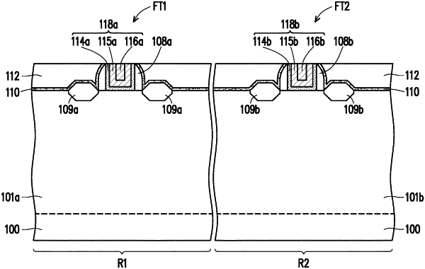
forming a first source/drain region on opposing sides of the first dummy gate structure within the first region and a second source/drain region on opposing sides of the second dummy gate structure within the second region, wherein a top surface of the first source/drain region formed over the first fin in the first region is substantially coplanar with a top surface of the second source/drain region formed over the second fin in the second region.
|