| CPC H01J 37/32495 (2013.01) [C23C 14/545 (2013.01); C23C 16/52 (2013.01); H01J 37/32715 (2013.01); H01J 37/32899 (2013.01); H01L 21/02274 (2013.01); H01L 21/0332 (2013.01); H01L 22/26 (2013.01); H01J 2237/3321 (2013.01); H01J 2237/3323 (2013.01)] | 19 Claims |

|
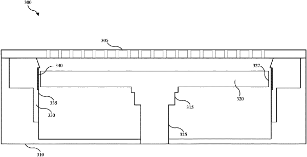
1. A semiconductor processing system, comprising:
a chamber body comprising sidewalls and a base;
a substrate support extending through the base of the chamber body, wherein the substrate support comprises:
a support plate; and
a shaft coupled with the support plate; and
a liner positioned within the chamber body and positioned radially outward of a peripheral edge of the support plate, wherein:
an inner surface of the liner comprises an emissivity texture, wherein the emissivity texture comprises a laser-textured pattern, the laser-textured pattern comprising etched and non-etch portions of the inner surface of the liner.
|