| CPC G06Q 10/04 (2013.01) [G05B 19/042 (2013.01); G06Q 50/06 (2013.01); H02J 3/0012 (2020.01); G05B 2219/2639 (2013.01); H02J 2203/20 (2020.01)] | 6 Claims |

|
1. A method for optimizing transformation of automation equipment in a power distribution network based on reliability, comprises:
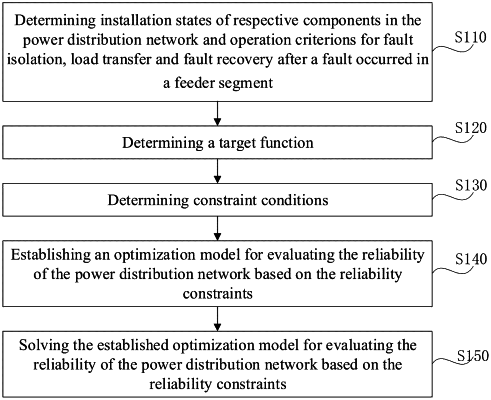
determining installation states of respective components in the power distribution network and operation criterions for fault isolation, load transfer and fault recovery after a fault occurred in a feeder segment;
determining a target function, the target function being a target function for Total of the power distribution network, as minimizing a total transformation cost C expressed by the following formula (1):
 where:
cijUp represents a transformation cost for upgrading equipment ij in the power distribution network;
Ω represents a set of all the equipment in the power distribution network, comprising a circuit breaker and switch;
xijA represents a 0-1 variation indicating an automatic status of the equipment ij after the transformation, with xijA indicating an automatic equipment and xijA=0 indicating a non-automatic equipment; and
xijA,E represents a 0-1 variation indicating the automatic status of the equipment ij before the transformation, xijA,E with indicating the automatic equipment and xijA,E=0 indicating the non-automatic equipment;
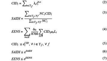
determining constraint conditions, the constraint conditions comprising reliability constraints, as expressed by the following formulas (2) to (7):
 where:
CIDi represents average outage time of a feeder segment i of a feeder line f in the power distribution network per year;
Υf represents a set of all feeder segments of the feeder line f;
λs represents a failure rate of a feeder segment s per year;
tiins represents an outage time in a failure scenario of the feeder segment s;
SAIDi represents an average outage time of the network per year;
NGi represents a number of users in the feeder segment i;
EENS represents an expected loss of load energy;
H represents a set of all load levels;
Δh represents hours for which the load level h lasts per year;
Ψ represents a set of all nodes in the power distribution network;
μh represents a peak load ratio of the load level h and μh≤1;
Li represents a peak load at the node i;
εiCID represents an upper limit for the average outage time of the feeder segment i per year;
εSAIDi represents an upper limit for the average outage time of the network per year; and
εEENS represents an upper limit for the expected loss of load energy of the network;
establishing an optimization model for evaluating the reliability of the power distribution network based on the reliability constraints in accordance with the target function and the constraint conditions; and
solving the established optimization model for evaluating the reliability of the power distribution network based on the reliability constraints to obtain an optimal solution of 0-1 variable xijA indicating an automatic status of the equipment ij after the transformation, as an optimization result of the automation transformation state of the circuit breaker and the switch, and to obtain optimal solutions of the customer interruption duration CIDi of the feeder segment i, the network average interruption duration SAIDI and the expected energy not supplied EENS, as an optimization result of the reliability index, so as to transform the automation equipment in the distribution network based on the optimization result of the automation transformation state and the reliability index,
wherein:
the power distribution network comprises at least one feeder line;
the circuit breaker that is capable of interrupting a fault current is installed at the head of each feeder line;
each feeder line is divided into a plurality of feeder segments via at least one interconnection switch that is not capable of interrupting the fault current;
at least one of the plurality of feeder segments is a feeder segment that is contained in a feeder corridor;
0 or 1 interconnection switch is provided between each feeder line and other feeder line; and
the distribution network comprises an automatic circuit breaker and an automatic switch which detects currents and voltages in interfaces at both ends of the feeder line and make response accordingly, and a non-automatic circuit breaker and a non-automatic switch which are operated manually, and
wherein, the step of determining installation states and operation criterions further comprises:
a) opening the automatic circuit breaker or the non-automatic circuit breaker at the head of the feeder line a feeder segment belongs to, upon the feeder segment fails, to interrupt the fault current, resulting in power outage in downstream nodes of the circuit breaker, and all automatic switches in the feeder line the feeder segment belongs to being opened;
b) entering an automatic operation stage upstream of fault and proceeding to step c) if the circuit breaker is the automatic circuit breaker, or proceeding to step g) if the circuit breaker is the non-automatic circuit breaker;
c) reclosing the automatic circuit breaker in the automatic operation stage in the upstream of fault;
d) in response to the reclosing operation not triggering a further tripping operation of the automatic circuit breaker, sensing a one-side normal voltage by the first automatic switch in a downstream of the automatic circuit breaker and closing the first automatic switch in a short interval, or in response to the reclosing operation triggering a further tripping operation of the automatic circuit breaker, proceeding to step g);
e) sensing the one-side normal voltage by other automatic switches and closing the other automatic switches sequentially on a timed interval after the first automatic switch downstream of the automatic circuit breaker is closed, until the closing operation of an automatic switch which has been just closed causes a second fault tripping, such that all circuit breakers in the upstream of the automatic switch which has been just closed are tripped, all the automatic switches in the feeder line are opened again, causing the automatic switch which has been just closed and caused the second fault tripping to be opened and locked in the open state;
f) reclosing the automatic circuit breaker again, and repeating the steps d) to e) until all switches in a non-locked state in the upstream of the fault are reclosed again, and entering an automatic operation stage in the downstream of fault;
g) in response to an automatic interconnection switch existing in the downstream of the fault, closing the automatic interconnection switch after a preset delay time after the fault occurred in the automatic operation stage in the downstream of fault;
h) in response to the closing operation of the automatic interconnection switch not triggering a tripping operation of the interconnection switch, sensing the one-side normal voltage by the first automatic switch in the upstream of the automatic interconnection switch and closing the first automatic switch in a short interval, or in response to the closing operation of the automatic interconnection switch triggering the tripping operation, proceeding to step k);
i) sensing the one-side normal voltage by other automatic switches and closing the other automatic switches sequentially on a timed interval after the first automatic switch in the upstream of the automatic interconnection switch is closed, until the closing operation of an automatic switch which has been just closed causes a tripping of the automatic interconnection switch, such that all the automatic switches in the feeder line in the downstream of fault are opened again, causing the automatic switch which has been just closed and caused the tripping of the automatic interconnection switch to be opened and locked in the open state;
(j) closing the automatic interconnection switch again, and repeating the steps h) to i) until all the automatic switches in an unlocked state in the downstream of fault are closed again, and entering a post-fault manual operation stage; and
(k) operating the non-automatic circuit breaker and the non-automatic switch manually in the post-fault manual operation stage, to further isolate the fault and to restore the affected load from the fault, such that the faulty feeder segment is restored, and the power distribution network are restored by operating the non-automatic switch and the non-automatic circuit breaker.
|