| CPC G02B 5/203 (2013.01) [G02B 5/201 (2013.01); G02B 5/28 (2013.01); G02B 27/12 (2013.01); H10K 50/858 (2023.02)] | 7 Claims |

|
1. A wavelength selection filter, comprising:
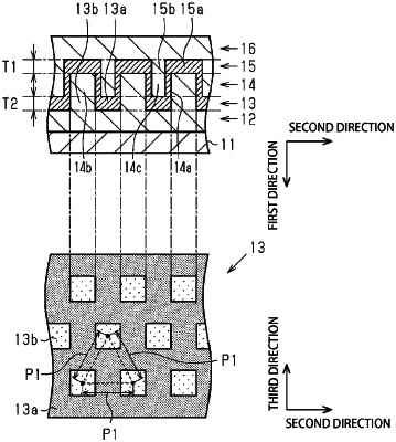
a projection-depression structure layer having, on a surface thereof, a projection-depression structure including a plurality of projection-depression elements being projections or depressions, the projection-depression elements being spaced from each other at a subwavelength period and arranged in a form of a two-dimensional lattice;
a high refractive index layer positioned on the projection-depression structure and having a surface shape following the projection-depression structure, the high refractive index layer including a first high refractive index section positioned on a bottom of the projection-depression structure and a second high refractive index section positioned on a top of the projection-depression structure; and
a filling layer filling surface projections and depressions of the high refractive index layer, wherein
n1>n2, n1>n3, and R1+R2>1,
a value of T1×{n1×R1+n2×(1−R1)} is a first parameter, a value of T2×{n1×R2+n3×(1−R2)} is a second parameter, and a ratio of the second parameter to the first parameter is 0.7 or more and 1.3 or less,
where T1 is a thickness of the first high refractive index section, T2 is a thickness of the second high refractive index section,
n1 is a refractive index of a material of the high refractive index layer, n2 is a refractive index of a material of the projection-depression structure layer, n3 is a refractive index of a material of the filling layer,
R1 is an area ratio occupied by the first high refractive index section in a cross section including the first high refractive index section and orthogonal to a thickness direction thereof, and R2 is an area ratio occupied by the second high refractive index section in a cross section including the second high refractive index section and orthogonal to a thickness direction thereof.
|