| CPC F04D 29/522 (2013.01) [F04D 19/002 (2013.01)] | 6 Claims |

|
1. A fan structure, comprising:
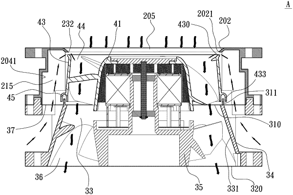
an upper frame having an upper-frame top portion, an upper-frame bottom portion, and an upper-frame wall portion internally defining a receiving space; and the upper-frame wall portion being provided on an inner side at positions corresponding to four corners of the upper-frame top portion with at least one recess, which is communicable with the receiving space;
a stationary blade frame being connected to a lower side of the upper frame and including a top portion, a bottom portion, a flared air passage, at least one inclined section, and a stator seat; the flared air passage being conical in shape and having a diametrical size increasing gradually from the top portion toward the bottom portion of the stationary blade frame and being enclosed in an air passage wall surface; each inclined section being radially inset from a respective one of four corners of the stationary blade frame corresponding to the four corners of the upper-frame top portion formed on the inner side of the upper-frame wall portion, and being radially outward and downward inclined from the top portion to the bottom portion of the stationary blade frame; the top portion of the stationary blade frame being connected to the upper-frame bottom portion end-to-end and having a stationary-blade-frame inlet and an upward flange extending around an outer periphery of the stationary-blade-frame inlet; and the stator seat being located in the flared air passage and having a shaft barrel provided thereon; and
an annular impeller located in the receiving space of the upper frame and rotatably connected to the shaft barrel of the stationary blade frame and accordingly, mounted on the stator seat; the annular impeller including a hub having a plurality of blades spaced on a circumferential outer surface of the hub, and an annular member connected to radially outer ends of the blades; the annular member having a lower rim facing toward and spaced from the upward flange formed around the stationary-blade-frame inlet, such that a middle gap is defined between the lower rim of the annular member and the upward flange at the stationary-blade-frame inlet; the hub and the annular member together defining between them an impeller air passage, the impeller air passage and the flared air passage of the stationary blade frame being communicable with each other to form an inner airflow path; the impeller member having an outer circumferential surface facing toward and spaced from the inner side of the upper-frame wall portion, such that at least one outer side passage is defined between the annular member of the annular impeller and the at least one recess respectively of the upper frame; the at least one outer side passage being located in the receiving space outside the impeller air passage; the at least one outer side passage and the at least one inclined section of the stationary blade frame together forming a respective outer airflow path that leads to an external environment; the at least one outer airflow path being communicable with the inner airflow path via the middle gap.
|