| CPC F04C 15/0096 (2013.01) [F04C 2/16 (2013.01); F04C 18/16 (2013.01); F04C 29/0014 (2013.01); F04C 29/021 (2013.01); F04C 29/028 (2013.01); F04C 2270/205 (2013.01)] | 10 Claims |

|
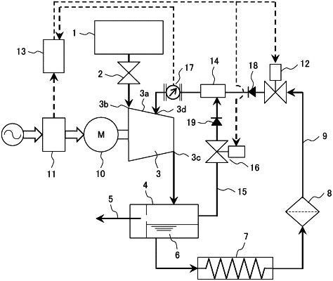
1. A liquid-cooled rotary compressor including a compressor main body that forms a compression chamber by a fixed wall and a rotor and a liquid injection path that injects a coolant into the compression chamber and adjusts a discharge flow rate by changing a load factor of the compressor main body, the liquid-cooled rotary compressor comprising:
a liquid amount adjusting unit that adjusts an amount of the coolant supplied from the liquid injection path to the compressor main body according to a change in the load factor of the compressor main body; and
a compressed gas supply path configured to supply compressed gas to a downstream side of the liquid amount adjusting unit in the liquid injection path,
wherein the compressed gas is supplied from the compressed gas supply path to the liquid injection path according to the amount of the coolant supplied to the compressor main body,
wherein the fixed wall is a casing of the liquid-cooled rotary compressor,
wherein the casing is provided with a suction port through which gas is sucked, a discharge port through which compressed gas is discharged, and an injection port through which liquid is injected into the compression chamber,
wherein the liquid injection path is connected to the injection port,
wherein the liquid injection path includes a first flow rate adjusting valve as the liquid amount adjusting unit and a gas-liquid mixing unit provided on a downstream side of the first flow rate adjusting valve,
wherein the compressed gas supply path is connected to the gas-liquid mixing unit, and
wherein a second flow rate adjusting valve is provided in the compressed gas supply path.
|