| CPC F02C 7/042 (2013.01) [B64D 33/02 (2013.01); F02C 7/057 (2013.01); B64D 2033/026 (2013.01); Y10T 137/0536 (2015.04)] | 14 Claims |

|
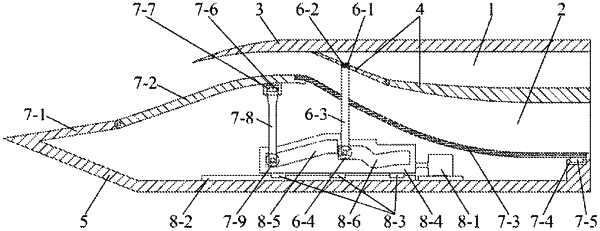
1. An internal-parallel inlet with mode conversion combined with variable geometry adjustment, comprising a high-speed channel extending from front to back, a low-speed channel positioned at an inner side of the high-speed channel and extending from front to back in parallel with the high-speed channel, a forebody compression surface, and a flow distribution plate of the high-speed/low-speed channel positioned between the high-speed channel and the low-speed channel; wherein the flow distribution plate comprises a fixed plate and a movable plate hinged to a front end of the fixed plate, and the movable plate swings inwards or outwards from a hinged position of the movable plate with the fixed plate; an outer wall surface of the high-speed channel is a high-speed channel cowl; an inner wall surface of the low-speed channel comprises a lower integrated surface hinged to a rear end of the forebody compression surface and a flexible diffusion section connected with a rear end of the lower integrated surface and extending backwards; a base is arranged on the inner sides of the forebody compression surface, the lower integrated surface and the flexible diffusion section; the base is provided with a driving device, a driving block connected with the driving device and a sliding rail bearing the driving block, and the driving block moves back and forth along the sliding rail under the driving of the driving device; a first driving rod positioned between an inner side of the lower integrated surface and the driving block and a second driving rod positioned between an inner side of the movable plate and the driving block are also arranged; a first guide groove and a second guide groove positioned behind the first guide groove are formed inside the driving block; the first guide groove comprises a first front end, a first middle position and a first rear end, the first front end is lower than the first middle position and the first rear end, the first middle position is lower than the first rear end, the second guide groove comprises a second front end, a second middle position and a second rear end, the second front end is higher than the second middle position and the second rear end, and the second rear end is higher than the second middle position;
one end of the first driving rod is fixed with the lower integrated surface, while a lower end of the first driving rod is hinged with the first guide groove through a first transverse shaft positioned in the first guide groove, and one end of the second driving rod is hinged with the movable plate, while a lower end of the second driving rod is hinged with the second guide groove through a second transverse shaft positioned in the second guide groove;
when one end of the first driving rod is positioned at the first front end, one end of the second driving rod is positioned at the second front end, and a front end of the movable plate abuts against an inner side of the high-speed channel cowl;
when the driving block moves forwards until one end of the first driving rod is positioned at the first middle position, one end of the second driving rod is positioned at the second middle position, the lower integrated surface is close to the high-speed channel cowl, and the front end of the movable plate abuts against an outer side of the flexible diffusion section;
when the driving block moves forwards until one end of the first driving rod is positioned at the first rear end, one end of the second driving rod is positioned at the second rear end, and the front end of the movable plate abuts against the outer side of the flexible diffusion section.
|