| CPC B41J 13/03 (2013.01) [B41J 11/0045 (2013.01); B41J 11/04 (2013.01); B41J 11/08 (2013.01); B41J 13/0018 (2013.01); B41J 13/0036 (2013.01); B41J 13/025 (2013.01); B41J 13/076 (2013.01)] | 8 Claims |

|
1. A recording device comprising:
a transport unit that transports a medium along a horizontal direction in a transport direction;
a medium supporting member that includes a supporting surface supporting the medium; and
a recording head that performs recording on the medium at a position facing the medium supporting member,
wherein the transport unit includes:
a transport roller pair formed of a transport driving roller and a transport driven roller provided upstream of the medium supporting member in the transport direction,
a discharge roller pair formed of a discharge driving roller and a discharge driven roller provided downstream of the medium supporting member in the transport direction, and
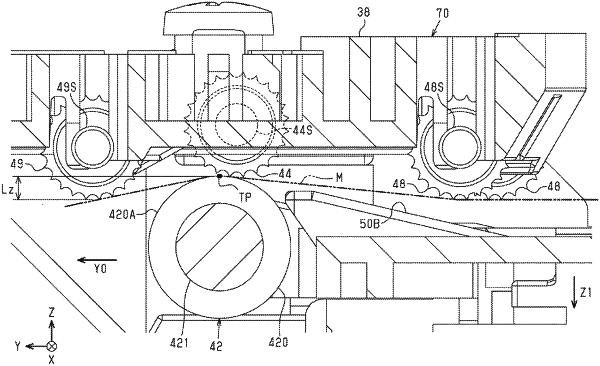
guide rollers provided downstream of the medium supporting member in the transport direction, and on the same upper side as the discharge driven roller with respect to a transport path of the medium, and driven to rotate by contact with the medium during transport,
the guide rollers are provided on both sides of the discharge roller pair in the transport direction,
at least one of the guide rollers is a first roller disposed upstream of the discharge roller pair in the transport direction, and at least one of the guide rollers is a second roller provided downstream of the discharge roller pair in the transport direction, and
a lower end of the second roller is positioned lower than the upper end of the discharge driving roller,
wherein a lower end of the first roller is positioned lower than the upper end of the discharge driving roller,
wherein positions of the first roller and the second roller are the same in the width direction.
|