| CPC H02M 1/08 (2013.01) [B60L 15/04 (2013.01); B60L 50/50 (2019.02); H02M 7/53871 (2013.01); H02P 27/06 (2013.01); B60L 2210/10 (2013.01); B60L 2210/40 (2013.01); H02M 3/158 (2013.01)] | 17 Claims |

|
1. An electric drive system comprising:
an electric machine;
a traction battery; and
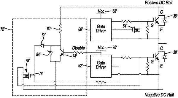
a power converter configured to transfer power between the electric machine and traction battery, and including a pair of series connected switches defining a phase leg, a pair of gate driver circuits configured to respectively provide power to gates of the series connected switches, a DC-link capacitor in parallel with the phase leg, a positive DC rail electrically connecting the DC-link capacitor and phase leg, and a clamping circuit directly connected to the positive DC rail and including a clamping switch, wherein the clamping circuit is configured to, responsive to one of the gate driver circuits being de-energized, activate the clamping switch with energy from the positive DC rail to clamp a gate of one of the series connected switches associated with the one of the gate driver circuits to another terminal of the one of the series connected switches to prevent the one of the series connected switches from achieving an ON state.
|