| CPC H02K 1/276 (2013.01) [H02K 21/14 (2013.01); H02K 29/03 (2013.01); H02K 2213/03 (2013.01)] | 12 Claims |

|
1. A permanent magnet auxiliary synchronous reluctance motor, comprising:
a stator portion comprising a stator core and a winding embedded in the stator core, the stator core having a stator tooth and a stator slot; and
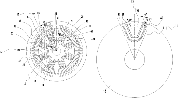
a rotor portion disposed in the stator portion, wherein a rotor body of the rotor portion is provided with a plurality of permanent magnet slot groups, the plurality of permanent magnet slot groups are evenly arranged along a circumferential direction of the rotor body, each of the permanent magnet slot groups is provided with multiple layers of permanent magnet slots, a distance between an end portion of a permanent magnet slot in a permanent magnet slot group and an end portion of an adjacent permanent magnet slot in an adjacent permanent magnet slot group is less than or equal to a width of a stator tooth shoe of the stator tooth, and a number of the permanent magnet slots per pole and per phase of the motor is two or three;
wherein a permanent magnet slot group comprises an outer layer of permanent magnet slot and an inner layer of permanent magnet slot, a magnetic conduction channel is formed between the outer layer of permanent magnet slot and the inner layer of permanent magnet slot, the inner layer of permanent magnet slots of two adjacent permanent magnet slot groups are arranged adjacently;
wherein the plurality of permanent magnet slot groups comprise a first permanent magnet slot group, the first permanent magnet slot group comprises a first inner layer of permanent magnet slot and a first outer layer of permanent magnet slot, a first magnetic conduction channel is formed between the first inner layer of permanent magnet slot and the first outer layer of permanent magnet slot;
wherein an end portion of the outer layer of permanent magnet slot and an end portion of the inner layer of permanent magnet slot are both disposed toward the outer edge of the rotor body, and magnetic isolation bridges having an equal width are formed between the outer layer of permanent magnet slot and the outer edge of the rotor body, and between the inner layer of permanent magnet slot and the outer edge of the rotor body;
wherein a distance from an end portion of the first outer layer of permanent magnet slot to the outer edge of the rotor body is H, a width of the end portion of the first outer layer of permanent magnet slot is M, and a width of the magnetic isolation bridge is H1, satisfying 0.4×M≤(H−H1)≤2×M.
|