| CPC G01L 1/2287 (2013.01) [H05K 1/0296 (2013.01); H05K 1/0393 (2013.01); H05K 1/167 (2013.01); H05K 2201/10151 (2013.01)] | 18 Claims |

|
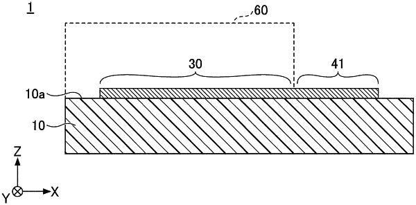
1. A strain gauge comprising:
a flexible resin substrate;
a functional layer formed of a metal, an alloy, or a metal compound, on one surface of the substrate;
a resistor formed as a film containing Cr, CrN, and Cr2N, on one surface of the functional layer; and
a pair of electrodes electrically connected to the resistor,
wherein each electrode includes a plurality of first patterns that are juxtaposed at predetermined intervals and that are electrically connected to each other,
wherein a plurality of second patterns of which longitudinal directions are toward a same direction as a longitudinal direction of each of the first patterns are disposed between opposing electrodes,
wherein the plurality of second patterns are electrically floating dummy patterns, and
wherein the plurality of second patterns of which the longitudinal directions are toward a same direction as the longitudinal direction of each first pattern are disposed, the second patterns being interposed between first patterns opposite each other, among the first patterns, and the first patterns opposite each other being from among given first patterns that constitute one of the electrodes and given first patterns that constitute another electrode.
|