| CPC F21V 23/06 (2013.01) [F21S 4/24 (2016.01); F21V 23/001 (2013.01); H01R 4/32 (2013.01); H01R 13/00 (2013.01); F21V 21/005 (2013.01); F21Y 2103/10 (2016.08); F21Y 2115/10 (2016.08); H01R 11/01 (2013.01)] | 5 Claims |

|
1. A terminal for a light system having a tape light, the terminal enables a connection of the tape light with at least one electric element, the terminal comprising:
a body having
a base,
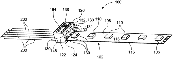
a first sidewall extending outwardly from the base and defining an opening to receive a portion of the tape light, a second sidewall extending outwardly from the base and arranged spaced apart from the first sidewall, wherein the first sidewall defines an opening that extends from the first sidewall towards the second sidewall; the opening facilitates an insertion of the tape light inside the housing, and the opening comprises a rectangular slot and is disposed proximate to the base of the housing; wherein the opening is configured for insertion of an RGB tape light and an RGBW tape light, the second sidewall defines five grooves extending inside the body from the second sidewall for receiving the at least one electric element and five slots extending from the first sidewall to the second sidewall, and arrayed between a third sidewall and a fourth sidewall, wherein the grooves are arrayed along a width of the second sidewall between the third sidewall and the fourth sidewall; and the plurality of slots is arranged in a staggered arrangement in a first row comprising two slots and a second row comprising three slots, and each of the five slots comprises a rectangular slot having greater height than width, and
a roof comprising an upper surface and arranged opposite to the base and defining
a plurality of cut-outs arranged proximate to the first sidewall and extending from the roof to the opening, wherein each cut-out comprises a first cut-out portion extending from the upper surface of the roof to the slot arranged directly below the cut-out, and a second cut-out portion extending from the associated slot to the opening through the partition wall; and
a plurality of holes extending from the upper surface of the roof through the body and intersecting the plurality of grooves and arranged proximate to the second sidewall and extending inside the body from the roof to the at least one groove, wherein the plurality of holes is arrayed in a single row between the third sidewall and the fourth sidewall, and each hole comprises a first hole portion extending from the upper surface of the roof to an associated slot arranged directly below the hole and a second hole portion extending from the associated slot to the groove arranged directly underneath the hole and through the partition wall; and
a plurality of rails arranged inside the body and extending from the first sidewall to the second sidewall intersecting the plurality of cut-outs of the body and the plurality of holes of the body, each rail includes a first hole arranged proximate to the second sidewall and a second hole arranged proximate to the first sidewall, wherein axes of the first holes of the rails align with axes of the holes of the body and axes of the second holes of the rails align with axes of the cut-outs of the body, each first hole of each rail extends from an upper surface of the rail to a lower surface of the rail, and each second hole of each rail extends from the upper surface of the rail to a lower surface of the rail, wherein the rails are arranged in a plurality of rows and in a staggered arrangement;
each of the grooves facilitates insertion of one of the plurality of wires inside the housing to enable the electrical connection of the wires with the plurality of rails; and the plurality of grooves is arranged between the five slots and the base of the housing.
|