| CPC F04B 45/10 (2013.01) [F04B 43/046 (2013.01); F04B 45/047 (2013.01); H10N 30/2047 (2023.02)] | 20 Claims |

|
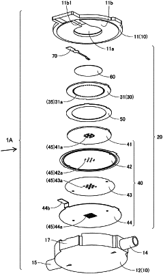
1. A pump, comprising:
a first vibrating body that has a plate shape;
a second vibrating body that has a plate shape and is opposed to the first vibrating body;
a peripheral wall portion connecting a peripheral portion of the first vibrating body with a peripheral portion of the second vibrating body;
a pump chamber positioned between the first vibrating body and the second vibrating body and defined by the first vibrating body, the second vibrating body, and the peripheral wall portion;
a driving body causing the first vibrating body and the second vibrating body to bend and vibrate to generate pressure fluctuation in the pump chamber; and
a housing that houses a driving unit composed of the first vibrating body, the second vibrating body, the peripheral wall portion, and the driving body, wherein
the housing includes a first wall portion positioned on a side opposite to a side where the second vibrating body is positioned when viewed from the first vibrating body, and a second wall portion positioned on a side opposite to a side where the first vibrating body is positioned when viewed from the second vibrating body,
the driving unit is disposed so as to divide a space inside the housing into a first chamber defined by the first vibrating body and the first wall portion, and a second chamber defined by the second vibrating body and the second wall portion,
the housing is provided with a first communication portion that communicates the first chamber with a space outside the housing, and a second communication portion that communicates the second chamber with a space outside the housing,
the first vibrating body is provided with a first hole portion that communicates the pump chamber with the first chamber,
the second vibrating body is provided with a second hole portion that communicates the pump chamber with the second chamber,
the first wall portion includes a first concave portion that opens toward the first vibrating body and that is opposed to a portion, including a central portion, of the first vibrating body, and a first circumferential portion that is annular and is adjacent to the first concave portion in a direction orthogonal to an axis line,
the first chamber includes a first wide portion defined by the first concave portion and a portion of the first vibrating body opposed to the first concave portion, and a first narrow portion defined by the first circumferential portion and a portion of the first vibrating body opposed to the first circumferential portion, and
the first narrow portion overlaps with at least part of the first vibrating body when viewed in a direction parallel to an extending direction of the axis line.
|