| CPC F04B 43/04 (2013.01) [F04B 43/046 (2013.01); F04B 49/22 (2013.01); F16K 7/17 (2013.01); F16K 15/14 (2013.01); H10N 30/2047 (2023.02); F04B 43/14 (2013.01); F16K 31/02 (2013.01)] | 22 Claims |

|
1. A fluid control device comprising:
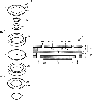
a valve including a first main plate, a second main plate, and a first side plate, and having a valve chamber, wherein one main surface of the second main plate faces one main surface of the first main plate, the first side plate connects the first main plate and the second main plate, and the valve chamber is comprised of the first main plate, the second main plate, and the first side plate, and wherein the first main plate has a first vent hole through which an inside and an outside of the valve chamber communicate with each other, and the second main plate has a second vent hole through which the inside and the outside of the valve chamber communicate with each other;
a pump including a diaphragm and a second side plate, and having a pump chamber, wherein the diaphragm is disposed to face another main surface of the first main plate, a piezoelectric element is disposed in the diaphragm, and the pump chamber is comprised of the first main plate, the diaphragm, and the second side plate, and wherein the pump chamber communicates with the valve chamber through the first vent hole; and
a valve body disposed in the valve chamber, wherein
when the one main surface of the second main plate is viewed from a front side of the one main surface of the first main plate,
the valve chamber includes a central region and an outer end region surrounding the central region,
the first vent hole is positioned in the central region and the second vent hole is positioned in the outer end region, or
the first vent hole is positioned in the outer end region of the valve chamber and the second vent hole is positioned in the central region of the valve chamber, and
the valve body is positioned between the first vent hole and the second vent hole,
the valve body is fixed to the first main plate or the second main plate in a state in which an end portion on a side of the outer end region or an end portion on a side of the central region is capable of vibrating, and
wherein the valve body is fixed to the first main plate or the second main plate at a fixed portion of the valve body, and wherein said fixed portion is not aligned with the first vent hole and the second vent hole in plan view.
|