| CPC F02B 23/0624 (2013.01) [F02B 23/0669 (2013.01); F02B 75/282 (2013.01); F02M 61/14 (2013.01); F02M 61/1806 (2013.01)] | 3 Claims |

|
1. An opposed-piston engine, comprising:
at least one cylinder;
a first piston disposed on one side in an axial direction in the at least one cylinder;
a second piston disposed on another side in the axial direction in the at least one cylinder;
an air supply port formed in a wall surface of the at least one cylinder on the one side in the axial direction in the cylinder;
an exhaust port formed in the wall surface of the at least one cylinder on the another side in the axial direction in the cylinder; and
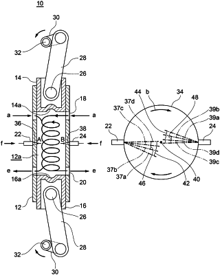
a first fuel injection device configured to inject fuel from the wall surface of the at least one cylinder into the cylinder, and a second fuel injection device disposed to be displaced in a circumferential direction so as to be opposite to the first fuel injection device across an axial center of the cylinder,
wherein each of the first fuel injection device and the second fuel injection device includes a plurality of injection holes having different injection directions, in a cross-section orthogonal to the axial direction, and
wherein if, in the plurality of injection holes of the first fuel injection device, an injection hole which is directed to a most upstream side with respect to a flow direction of a swirl flow formed in the cylinder is defined as a first upstream injection hole, and an injection hole directed to a most downstream side with respect to the swirl flow is defined as a first downstream injection hole;
an angular region demarcated by a direction directed by the first upstream injection hole and a direction directed by the first downstream injection hole is defined as a first injection region;
in the plurality of injection holes of the second fuel injection device, an injection hole which is directed to a most upstream side with respect to the flow direction of the swirl flow formed in the cylinder is defined as a second upstream injection hole, and an injection hole directed to a most downstream side with respect to the swirl flow is defined as a second downstream injection hole; and
an angular region demarcated by a direction directed by the second upstream injection hole and a direction directed by the second downstream injection hole is defined as a second injection region,
the direction directed by the first downstream injection hole is configured to pass through the second injection region; and
the direction directed by the second downstream injection hole is configured to pass through the first injection region.
|